
Description
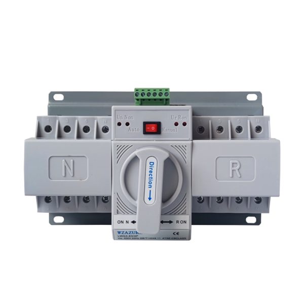
Automatic Transfer Switch 4P 63A — Three Phase ATS / Changeover Switch for Solar, Generator and Mains
The Automatic Transfer Switch 4P 63A — alternatively known as the Three Phase Automatic Changeover Switch 63A, Four Pole ATS 63A, or ATS 4P 63A — is the three-phase version of the automatic backup switching device that has become standard in Kenyan installations seeking continuous power. While its single-phase 2P sibling handles residential and small commercial premises under about 14 kVA, this 4-pole variant addresses the larger band of three-phase installations: medium-to-large residences with three-phase service, commercial buildings drawing balanced three-phase load, agricultural smallholdings with three-phase pump and processing equipment, and the growing class of three-phase hybrid solar installations on Kenyan commercial rooftops.
The 4-pole configuration switches all three line conductors (L1, L2, L3) plus the neutral conductor simultaneously, giving complete galvanic isolation between the primary and backup sources during every transfer event. This neutral-switching capability matters because three-phase installations almost always include single-phase outgoing ways downstream of the ATS — lighting circuits on one phase, kitchen sockets on another, individual appliances on each — and switching the neutral together with the lines is the correct practice for any installation with mixed three-phase plus single-phase distribution. The three-pole equivalent at the same current rating handles pure three-phase loads only, where no single-phase circuits route downstream from the ATS.
Why three-phase Kenyan installations are choosing automatic switching
Three-phase service connections used to be reserved for industrial premises and large institutional buildings in Kenya. That has changed quickly. Upmarket residential properties with multi-zone air conditioning, electric cookers, large solar installations, and three-phase EV charging now routinely choose three-phase service for the load-balance benefits it provides. Small offices, salons with heavy heating loads, dairy parlours, and commercial premises with three-phase machinery have followed the same path. The backup needs of these installations cannot be served by a single-phase ATS — the three-phase service must be switched in its entirety, including all three line conductors and the neutral, by a properly rated three-phase transfer device. The 4P 63A ATS occupies the most populous slot in this market band, suiting three-phase loads from approximately 25 kVA up to the 43 kVA upper limit of the rating.
Where the 4P 63A three-phase ATS belongs in your installation
- Three-phase hybrid solar with grid + battery: The ATS coordinates between the national grid supply and the AC output of a three-phase hybrid inverter (typically 10 kW to 20 kW) so that the building rides through grid outages on solar-and-battery power without operator intervention.
- Three-phase generator standby installations: Connects the three-phase national grid, the three-phase generator output, and the building’s main distribution board. The ATS senses grid loss, signals the generator to auto-start, waits for stable three-phase output, then transfers the load.
- Three-phase solar + generator + grid (three-source): Common in upmarket residential and small-commercial installations seeking maximum continuity. Solar provides daytime primary, the grid handles evenings and cloudy days, and the generator covers extended outages with depleted battery storage.
- Multi-tenant building common-area supplies: Where the three-phase incoming service feeds common-area lighting, lifts, water pumps, and service equipment that must remain operational during outages.
- Dairy parlours, milking sheds, and farm processing equipment: Three-phase agricultural installations where loss of refrigeration or milking infrastructure during an outage has direct revenue consequences.
- Three-phase office and clinic standby installations: Medium-sized commercial premises drawing balanced load across three phases, where the workday cannot tolerate a manual changeover delay.
- Small commercial retail, supermarket, and hospitality premises: Three-phase customer-facing operations where continuous trading matters and even brief outages disrupt customer experience.
- Mid-size workshops and light-manufacturing premises: Three-phase production floors where machine stops and restarts incur quality, scheduling, and maintenance costs that quickly justify the ATS investment.
How the 4-pole transfer device differs from its 2-pole sibling
The mechanical architecture of the 4P 63A ATS is similar in principle to the 2P version but scaled up to handle the additional poles. Inside the housing sit two contactor banks (primary and backup), each with four switched contacts arranged to handle three line conductors plus the neutral. A common mechanical interlock bar runs across both banks, physically preventing both banks from closing their contacts at the same time regardless of what the electronic controller commands. The controller circuit monitors voltage on every phase of both sources, applying the transfer logic across all three phases simultaneously — a fault on any one phase of the primary source triggers transfer of all four poles together.
Three operational behaviours distinguish the 4-pole device from the 2-pole. First, three-phase voltage sensing — the controller must sample voltage on each phase independently to detect phase-loss conditions where one or two phases drop while the third remains. Second, phase rotation verification — the controller may verify that both sources have matching phase rotation (R-Y-B sequence consistent on both inputs) before allowing transfer, since reverse rotation on the backup would damage downstream three-phase motors. Third, neutral switching — the fourth pole carries the neutral conductor independently, which is critical for any installation with single-phase outgoing ways downstream of the ATS.
Technical Specifications
| Parameter | Specification |
|---|---|
| Product Type | Automatic Transfer Switch (ATS) / Automatic Changeover Switch |
| Pole Arrangement | 4P — three lines plus neutral, all switched simultaneously |
| Trip Current per Pole (In) | 63 amperes continuous |
| Three-Phase Capacity | Up to approximately 43 kVA total at 400V three-phase |
| System Voltage Range | 400V phase-to-phase / 230V phase-to-neutral |
| Frequency Window | 50 Hz and 60 Hz dual rating |
| Operating Modes | Automatic / Manual (front-face selectable) |
| Sense + Switch Time | Roughly 0.5–2 seconds end-to-end (typical) |
| Return-to-Primary Delay | Programmable 5–30 seconds on advanced variants |
| Voltage Sense Threshold | Configurable, typically ~180V per phase |
| Phase Loss Detection | Independent monitoring on each of the three phases |
| Mechanical Interlock | Common bar across all four poles prevents simultaneous source connection |
| Mounting Method | Snap-fit 35mm symmetrical DIN rail |
| Panel Footprint | Roughly 8 modules of 18mm width on the rail |
| Per-Terminal Conductor Capacity | Solid or stranded copper accepted to 25mm² |
| Recommended Per-Phase Supply Cable | Minimum 16mm² copper; 25mm² advised on cable runs above 15 metres |
| Rated Mechanical Endurance | ~10,000 source-transfer cycles |
| Rated Electrical Endurance | ~6,000 transfer cycles when loaded to nominal current |
| Insulation Rated Voltage (Ui) | 500V |
| Impulse Rated Voltage (Uimp) | 4 kV typical |
| Pollution Class | Class 2 sealed indoor installation |
| Ambient Temperature Range | −5°C to +40°C |
| Status Indicators | Per-source LED plus mechanical position window |
| Auto-Start Output | Dry contact closure for generator remote-start input |
| Compliance Reference | IEC 60947-6-1 (transfer switching equipment standard) |
Engineering Features That Matter for Three-Phase Operation
- Independent per-phase voltage monitoring — the controller samples each of the three phases separately, detecting genuine phase-loss conditions where one or two phases drop while a third remains live (a common Kenyan grid event that single-phase sensing would miss).
- Common-trip across all four poles — a fault detected on any one phase or the neutral triggers transfer of every pole together, preventing the dangerous partial-phase condition where some loads continue running on remaining phases while others lose supply.
- Mechanical interlock with belt-and-braces design — a physical steel bar prevents both contactor banks from closing simultaneously, regardless of any electronic controller failure. The interlock is independent of the controller and operates even if the controller loses its own supply.
- Phase rotation verification (on advanced variants) — confirms both primary and backup sources have matching R-Y-B rotation before allowing transfer. Critical because reverse rotation would spin three-phase motors backwards and cause mechanical damage.
- Neutral switching for mixed-load installations — the dedicated fourth pole handles the neutral conductor independently, supporting any three-phase installation with single-phase outgoing ways downstream.
- Generator auto-start dry-contact output — a clean, voltage-free contact closure available on terminals dedicated for the generator remote-start interface, wires directly to the generator control panel without intermediate relays.
- Compact eight-module footprint — substantial but manageable, fitting in any three-phase distribution panel with adequate spare rail width. Significantly more compact than the cabinet-mounted ATS units traditionally used at this current rating.
- Same physical depth as smaller DIN-rail devices — installs flush in panels alongside MCBs, RCDs, and meters for a consistent professional appearance.
- Universal compatibility with three-phase hybrid inverters — works alongside the AC output of any modern grid-tie or hybrid solar inverter that supports grid-interactive mode.
Typical Kenyan Three-Phase Installations Using This ATS
- Three-phase hybrid solar systems pairing 10 kW to 20 kW hybrid inverters with the national grid in upmarket residences across Karen, Runda, Muthaiga, Lavington, and Spring Valley
- Three-phase generator standby installations at commercial premises drawing balanced load up to about 40 kVA peak — small offices, clinics, schools, and retail outlets
- Dairy parlour and farm processing installations where the three-phase service powers milking equipment, refrigeration, lighting, and water pumps
- Multi-tenant building common-area panels coordinating backup power to corridor lighting, lifts, common-area sockets, and security infrastructure
- Three-source backup arrangements at upmarket residences combining solar (daytime), grid (evenings), and generator (extended outages) on a three-phase service
- Small commercial retail and hospitality premises with mixed three-phase plus single-phase distribution drawing 25 to 40 kVA peak
- Hotels, restaurants, and small institutional facilities with three-phase HVAC, kitchen equipment, and lighting that benefit from continuous power
- Light manufacturing and workshop premises running three-phase machinery where production stops have measurable cost impact
- Three-phase pump houses on commercial agricultural sites where the borehole or irrigation pump must remain operational during outages
- Server rooms and small commercial data installations with three-phase rack power feeds requiring uninterrupted operation
Installation Notes
Installation of the 4P 63A three-phase ATS follows the same disciplined approach as any three-phase electrical work, with several additional considerations specific to transfer switching. Eight points govern correct setup. First, position — the ATS sits between the two three-phase source supplies (national grid primary on one side, generator or inverter backup on the other) and the building’s three-phase main distribution board. Second, conductor sizing — at 63 amperes continuous per phase plus neutral, the supply cables need 16mm² copper minimum per conductor on short runs, stepping to 25mm² where the cable exceeds about fifteen metres or passes through warm building voids. Third, phase rotation — verified with a rotation indicator on both supply sources before any wiring is permanent; both sources must have matching R-Y-B sequence at the ATS terminals. Fourth, terminal torque — apply the manufacturer’s specified value with a calibrated torque tool across all twelve terminals (three primary + neutral, three backup + neutral, three load + neutral). Fifth, neutral connection — all three neutrals (primary, backup, load) terminate at the dedicated fourth-pole terminals of the ATS; never bypass the neutral through the panel’s neutral bar. Sixth, generator coordination — for installations with a three-phase generator, the auto-start dry contact wires directly to the generator’s remote-start input following the generator manufacturer’s terminal documentation. Seventh, voltage sense per phase — confirm the sense threshold setting is appropriate for typical supply voltage on each phase, particularly important in areas where one phase may chronically run lower than the other two. Eighth, return delay — set generously at 15 to 30 seconds to prevent hunting between sources during marginal grid recovery conditions.
For three-phase hybrid solar installations, the ATS interfaces with the inverter through the inverter’s three-phase AC output. The inverter must be configured for grid-tie or grid-interactive mode rather than pure off-grid, allowing it to sense the grid presence and synchronise its output. The phase rotation at the inverter output must match the rotation at the grid supply — most modern three-phase hybrid inverters detect a rotation mismatch and refuse to clock onto the supply, but verifying rotation manually before commissioning eliminates one source of commissioning delay.
For three-phase generator installations, the auto-start interface is the single most common source of commissioning issues. The ATS provides the dry contact closure that signals the generator to start; the generator’s control panel performs the actual engine start, waits for stable output, and signals readiness through its alternator output. Different generator brands use different remote-start terminal conventions — some require a closure to start, some require an opening to start, some use a momentary pulse, and others require a sustained closure for the duration of the demand. Consult the generator’s installation manual for the specific terminal documentation and any required pull-up resistors or signal conditioning.
Designing a three-phase solar backup, generator standby, or multi-source installation?
Get a complete three-phase single-line diagram with the ATS correctly positioned, cable sizes specified per phase, and inverter or generator integration mapped — use our Solar Calculator for system-wide sizing, or describe your backup architecture through My Quote for a turnkey panel design with the ATS, MCBs, RCDs, and cable schedule.
