

Description
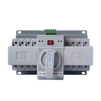
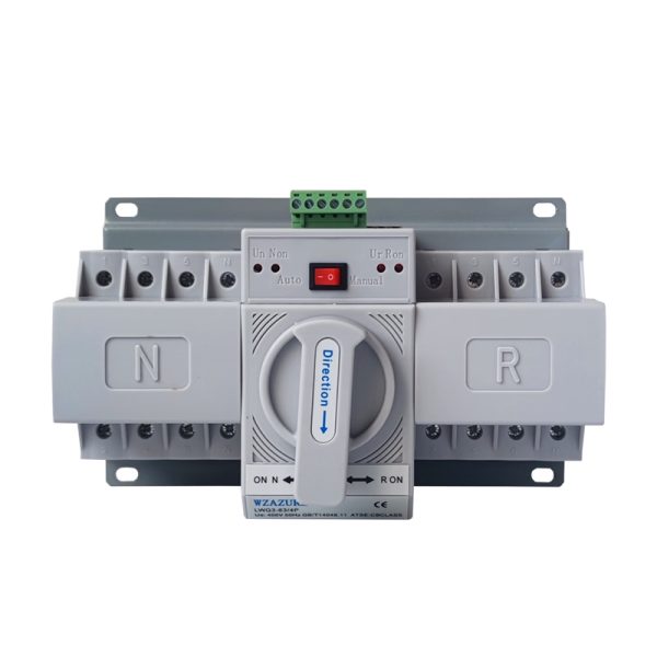
Automatic Transfer Switch 2P 63A — ATS / Changeover Switch for Solar, Generator and National Grid Backup
The Automatic Transfer Switch 2P 63A — equally searched as Automatic Changeover Switch 63A, ATS 2P 63A, or simply single-phase changeover switch — is the device that automatically switches your building’s supply between two power sources without operator intervention. The moment the primary supply fails, the ATS detects the loss within milliseconds, disconnects the dead source, and connects the backup source — restoring power to the loads typically within half a second to two seconds depending on configuration. When the primary supply returns, the device automatically switches back, leaving the backup source on standby for the next outage.
For Kenyan installations specifically, this ATS sits at the heart of three increasingly common backup scenarios. First, the standard hybrid solar setup, where the device toggles between the national grid and the AC output of a hybrid solar inverter that draws from battery storage during outages. Second, the conventional generator backup, where the ATS waits for the national grid to fail and then signals the generator to start before transferring the load. Third, the three-source arrangement common in upmarket installations, where solar serves as the daily primary, the grid as the secondary, and a standby generator as the deep-outage fallback — with the ATS coordinating the changeover sequence across all three.
Why an ATS belongs in every Kenyan backup installation
Manual changeover switches have been the norm in Kenyan installations for years — a wall-mounted lever that the homeowner or operator throws when the grid fails. The problem is well-known: the changeover usually happens fifteen to thirty minutes after the outage starts, by which time the fridge has warmed up, the office Wi-Fi has rebooted, the security system has cycled, and the inverter has been running on battery while the grid silently came back hours ago. An automatic transfer switch eliminates this gap. The device runs unattended in the background, switches sources within seconds of any change, and returns the system to the primary source when normal supply resumes — keeping the backup source available for the next event rather than draining it unnecessarily.
Where this 2P 63A ATS belongs in your installation
- Hybrid solar + national grid (most common Kenyan use): The ATS sits between your hybrid inverter’s AC output, the incoming national grid supply, and the building’s main distribution board. When the grid drops, the inverter holds the loads through battery storage and the ATS confirms the switch; when the grid returns, the ATS hands the load back and the inverter recharges the battery from the grid.
- Generator + national grid (traditional backup): Connects between the grid, the generator output, and the consumer unit. The ATS senses grid loss, signals the generator to start (via a separate auto-start panel), waits for stable generator voltage, then transfers the load. On grid return, it reverses the sequence and signals the generator to stop after a cool-down period.
- Solar + generator + national grid (three-source): Common in upmarket residential and small commercial installations where minimal downtime is critical. The ATS prioritises solar during the day, falls back to the grid at night when the battery is depleted, and brings in the generator only during extended grid outages with depleted battery storage.
- Office and clinic standby installations: Where uninterrupted operation matters but a full uninterruptible power supply (UPS) would be oversized for the load profile.
- Salons, barbershops, and retail premises: Where customers expect continuous operation during the workday and even short outages disrupt service.
- Rural premises with intermittent grid: Where the grid drops several times per week and operator-managed changeover becomes operationally exhausting.
- Server rooms and IT installations: Where the ATS works upstream of a smaller UPS to handle outages beyond the UPS battery window.
How the ATS works inside the panel
A 2-pole automatic transfer switch contains two main mechanical assemblies — a contactor block that physically connects either the primary source or the backup source to the load, and a controller that monitors voltage on both sources and decides which to connect. The contactor block is mechanically interlocked: a steel arm physically blocks both source contacts from closing at the same time, even if the controller tries to command it. This interlock matters because connecting two power sources simultaneously creates a parallel circuit between them, which can damage the generator, back-feed the grid (dangerous to utility workers during outages), and trip every protective device in the panel.
The controller side runs continuously, sampling voltage on both inputs many times per second. When the primary source voltage drops below a configurable threshold (typically around 180 volts on a 230V supply), the controller waits a short delay to confirm the loss is genuine rather than a brief sag, then commands the contactor to release the primary and engage the backup. The transfer takes between 0.5 and 2 seconds depending on the device variant. When the primary returns, the controller waits a longer delay (typically 5 to 30 seconds to confirm stable return) before switching back to the primary and releasing the backup.
Technical Specifications
| Specification | Value |
|---|---|
| Product Type | Automatic Transfer Switch (ATS) / Automatic Changeover Switch |
| Pole Configuration | 2P — switches live + neutral on each source |
| Rated Current (In) | 63 amperes continuous per pole |
| System Capacity (Single Phase) | Up to approximately 14 kVA on 230V |
| Rated Voltage | 230V AC single-phase / 400V AC compatible |
| Frequency Range | 50 Hz and 60 Hz |
| Operating Modes | Automatic / Manual (selectable via front switch) |
| Transfer Time (typical) | 0.5 to 2 seconds, sense + switch |
| Return Delay (typical) | 5 to 30 seconds (programmable variant) / fixed (basic variant) |
| Voltage Sense Threshold | Typically ~180V (configurable on advanced units) |
| Mechanical Interlock | Yes — prevents simultaneous source connection |
| Mounting | 35mm DIN rail (snap-fit, no tools required) |
| Panel Footprint | ~4 standard 18mm modules |
| Terminal Cable Capacity | Up to 25mm² stranded copper per terminal |
| Recommended Supply Conductor | 16mm² copper minimum; 25mm² for runs above 15m |
| Mechanical Operating Life | Approximately 10,000 transfer cycles |
| Electrical Operating Life | Approximately 6,000 transfer cycles under rated load |
| Insulation Rated Voltage | 500V |
| Pollution Degree | Class 2 (sealed indoor panel) |
| Ambient Operating Range | −5°C to +40°C |
| Status Indicators | LED status for each source, plus mechanical position window |
| Compliance Reference | IEC 60947-6-1 (transfer switching equipment standard) |
Key Features That Matter
- True automatic operation with manual override — runs unattended in the background but can be set to manual mode via the front-face switch for maintenance, generator testing, or commissioning work.
- Mechanical interlock — a physical steel bar prevents both supply contacts from closing simultaneously, eliminating the dangerous parallel-source condition that can damage generators and create back-feed hazards for utility workers.
- Dual-pole switching — both the live and the neutral conductors are physically broken on changeover, giving complete electrical isolation between sources during transfer.
- Fast transfer time — sense-and-switch typically completes within 0.5 to 2 seconds; brief enough that most computers, LED lighting, and electronic appliances ride through the transfer without rebooting.
- Programmable delays on advanced variants — configurable sense delay (to ignore brief grid sags) and configurable return delay (to confirm grid is genuinely stable before switching back).
- LED source-status indicators — visible front-face indicators show which source is currently connected, simplifying fault diagnosis without opening the panel.
- Wide cable terminal range — accepts 16mm² to 25mm² copper conductors at all six terminals (two primary, two backup, two load).
- Standard DIN-rail format — fits any existing distribution panel that has four spare modules available, no panel modification required.
- Operates across both 230V and 400V systems — usable on single-phase services or on a single phase taken from a three-phase supply.
Common Kenyan Installation Scenarios
- Hybrid solar systems pairing a 5 kW to 10 kW single-phase hybrid inverter (such as our Vestwood hybrid inverter range) with the national grid, where the ATS handles seamless backup switching
- Residential and small commercial generator installations where the ATS coordinates auto-start of a 5–15 kVA standby generator on grid failure
- Office, salon, retail, and clinic premises drawing 14 kVA peak load with critical uptime requirements during the workday
- Three-source backup installations combining solar (daytime primary), grid (night standby), and generator (extended outage fallback)
- Rural homes and farm steadings with intermittent national grid where automatic switching eliminates the operator burden of frequent manual changeover
- Server rooms and IT cabinets upstream of UPS units, handling sustained outages beyond UPS battery capacity
- Apartment block common-area panels switching corridor lighting and security between grid and backup during outages
- Refrigeration-critical premises (butcheries, pharmacies, milk parlours) where the ATS prevents cold-chain breaks during routine power events
Installation Notes
The ATS must be installed by an electrician registered with the Energy and Petroleum Regulatory Authority. Six points govern correct installation. First, position — the ATS sits between the two source supplies (primary on one side, backup on the other) and the building’s main distribution board. The primary source connects to the line/grid side of the ATS; the backup source (generator output or hybrid inverter AC output) connects to the standby side; the load side feeds your consumer unit. Second, conductor sizing — at 63 amperes continuous, the supply cable from each source needs 16mm² copper minimum, stepping to 25mm² where the cable run exceeds about fifteen metres. Third, terminal torque — apply the manufacturer’s specified value with a calibrated torque screwdriver across all six terminations. Fourth, generator coordination — for installations with a generator, the ATS auto-start contact (a dry contact closure available on most ATS units) wires to the generator’s remote-start input, which is documented in the generator manufacturer’s installation manual. Fifth, voltage sense calibration — verify the voltage sense threshold is set appropriately for your typical supply voltage, particularly important in areas with chronic low-voltage conditions where the ATS may otherwise trigger unnecessarily. Sixth, return delay setting — leave at the recommended 15–30 seconds to allow the grid to stabilise after restoration before switching back.
For hybrid solar installations, the ATS interfaces with the inverter through the inverter’s AC output terminals. The inverter must be configured for grid-tie or grid-interactive mode (not pure off-grid) so that it can sense the grid and synchronise to it. The ATS handles the physical changeover; the inverter handles the energy source selection (battery vs. solar vs. grid). Both devices coordinate naturally when configured correctly. Consult the inverter installation manual for the specific ATS interface requirements of your inverter model.
Designing a solar backup, generator changeover, or three-source installation?
Get a full single-line diagram with the ATS correctly positioned, cable sizes specified, and inverter integration mapped out — use our Solar Calculator for system-wide sizing, or describe your backup goals through My Quote for a complete panel design with the ATS, MCBs, and cable schedule.
