Description
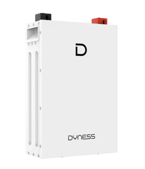
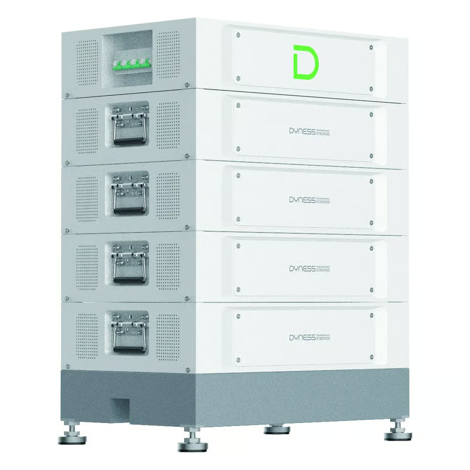
The Dyness Stack100 SBDU100 is the control and disconnect unit for a Stack100 high voltage cluster. It is fitted last, sitting on top of the stacked modules, and everything the cluster does on the outside happens through it.
It is not a battery. It contains no cells and stores no energy. That is worth stating plainly, because it is sometimes listed in battery categories, and a buyer who orders it expecting 5.12 kilowatt hours receives a switchgear box instead. The energy lives in the modules underneath it.
What it does is the switching, the protection and the conversation with the inverter.
- The DC breaker that isolates the whole cluster, acting as its master switch
- The positive and negative terminals carrying power out to the inverter
- The communication port that runs CAN and RS485 to the inverter
- Parallel ports, in and out, for systems built from more than one cluster
- The wake button that brings the system up
- The power switch for the management electronics
- The touch down earthing point, located on its upper face
- The wireless antenna for the monitoring application
One is required per cluster, and a cluster runs from three modules up to fifteen. Every module reports through it and connects through it, so a first installation needs exactly one.
The package is not only the unit. It ships as a set containing the control unit itself, the standard base the column stands on, the mounting brackets, the interconnecting cables and the manual. That matters when comparing offers, because the base is the part most often queried and it is already included here.
Dyness Stack100 SBDU100: Package Contents, Fitment and Cluster Planning
1. What Ships In The Package
Included as standard
- The SBDU100 control and disconnect unit itself
- The standard base, 590 by 390 by 100mm, which the column stands on
- Mounting brackets for securing the assembly
- The interconnecting cables for the column
- The installation manual
Supplied separately when the layout calls for it
- The expansion package, for arrangements built across two columns
- An expansion base, which is a different part from the standard one
- An expansion cover, usable only with an expansion labelled base
- The parallel cable linking the two columns together
- Additional series cables for the second column
The two base types are not interchangeable. An expansion cover stacked onto a standard base is specifically prohibited, because the circuit path through the assembly is broken by the mismatch. Where a layout grows later, the parts have to match the arrangement rather than simply be added to it.
2. Technical Specifications
Dyness publishes specifications for this unit at package and system level rather than as a standalone component table. The figures below are labelled by what each one actually applies to, and the rows the manufacturer does not publish are shown as such rather than estimated.
| Parameter | Value | Applies to |
|---|---|---|
| Model | SBDU100 | The unit |
| Function | Control and disconnect unit for one cluster | The unit |
| Dimensions | 590mm wide, 390mm deep, 133.5mm tall | The unit |
| Base dimensions | 590mm wide, 390mm deep, 100mm tall | Included base |
| Position in column | Fitted last, above the top module | The unit |
| Quantity required | One per cluster | The unit |
| Modules per cluster | 3 minimum, 15 maximum | The unit |
| Protection device | DC breaker serving as cluster master switch | The unit |
| Inverter connection | Positive and negative terminals, CAN and RS485 | The unit |
| Parallel connection | Dedicated in and out ports | The unit |
| Earthing | Touch down point on the upper face | The unit |
| Unit weight | Not published by the manufacturer | The unit |
| Standalone voltage rating | Not published separately from the cluster | The unit |
| Standalone current rating | Not published separately from the cluster | The unit |
| Breaker rating in amperes | Not published | The unit |
| Nominal cluster voltage | 153.6V to 768V, at 51.2V per module | The cluster |
| Operating voltage | 134V to 864V across the full range | The cluster |
| Energy per cluster | 15.36kWh to 76.8kWh | The cluster |
| Maximum current | 100A, charge and discharge | The cluster |
| Recommended current | 50A | The cluster |
| Peak current | 125A for 2 minutes at 25C | The cluster |
| Clusters in parallel | Up to 12, reaching 921.6kWh | The system |
| Communication | CAN or RS485, with built in wireless and app updates | The system |
| Protection level | IP20, indoor positions only | The system |
| Column dimensions | 590 by 390 by (233 plus 133 times the module count) mm | The cluster |
| Certification | CE-EMC, CE-RED, IEC 62619, IEC 63056, IEC 62477, IEC 62040, UN38.3 | The system |
| Module it serves | S51100, 51.2V, 100Ah, 5.12kWh, 47kg each | The modules |
On the unpublished rows: the weight of this unit is genuinely absent from both the datasheet and the user manual, where only the battery module carries a figure. Published numbers for it do circulate, but they disagree with one another, so none appear here. Section six gives the weight that actually governs siting, which is the column total.
3. Key Points
- It is the control and disconnect unit, holding no cells and storing no energy
- Every cluster of three to fifteen modules needs exactly one
- It is fitted last and sits above the top module, not underneath
- The standard base ships with it rather than being bought separately
- It carries the DC breaker that isolates the whole cluster
- It is the single point at which the cluster meets the inverter
- Its parallel ports are what allow clusters to work together
- It occupies one module layer of height, at 133.5mm
- It is ordered on its own when a system is extended or repaired
- Every Stack100 quotation from Bicity Solar includes it by default
4. Ceiling Height, The Constraint Most Quotes Miss
Because this unit adds a full module layer on top of the stack, the finished column is always taller than the module count alone suggests. In Kenyan rooms that frequently decides how much storage will physically fit.
The column stands on a 100mm base, and every layer above it, modules and control unit alike, is 133.5mm. A further 200mm of clear space is required above the unit for installation access and heat dissipation.
| Modules | Energy | Column height | Floor to ceiling needed | Fits a 2.4m ceiling |
|---|---|---|---|---|
| 3 | 15.36kWh | 634mm | 834mm | Yes |
| 6 | 30.72kWh | 1,035mm | 1,235mm | Yes |
| 8 | 40.96kWh | 1,302mm | 1,502mm | Yes |
| 10 | 51.2kWh | 1,569mm | 1,769mm | Yes |
| 12 | 61.44kWh | 1,836mm | 2,036mm | Yes |
| 14 | 71.68kWh | 2,103mm | 2,303mm | Yes, with little room spare |
| 15 | 76.8kWh | 2,236mm | 2,436mm | No |
A full fifteen module column does not fit under a standard 2.4 metre ceiling. It needs 2,436mm and a 2.4 metre room offers 2,400mm, so the installation fails on height before anything electrical is considered. Fourteen modules clear it, though with very little room to work above the unit.
There is a second reason the tall column is often the wrong answer. Above twelve modules, splitting the installation across two columns is the recommended arrangement rather than merely an option, which brings the height down sharply and makes the whole assembly easier to live with.
5. How Many Units A Layout Needs
For a single column the rule is simple. One control unit serves one cluster of three to fifteen modules, so a system of any height inside that range needs exactly one.
Two columns usually still need only one. The manufacturer’s configuration table lists two column arrangements with a single control unit package, adding an expansion package rather than a second unit, and the guidance for those builds asks for two bases and the extension cables. So splitting a column generally costs an expansion package, not another control unit.
| Arrangement | Modules | Control units | Also required |
|---|---|---|---|
| Single column, small | 3 to 8 | 1 | Nothing further |
| Single column, large | 9 to 12 | 1 | Nothing further |
| Two columns, recommended above 12 | 13 to 15 | 1 | Expansion package and a second base |
| Several clusters in parallel | Up to 12 clusters | 1 per cluster | Parallel cabling between clusters |
The distinction between a column and a cluster is what governs the count. A cluster is one electrical group managed by one control unit, and it may be arranged as one column or split across two. Separate clusters are a different matter: paralleling several of them, up to twelve in total, means one control unit each.
Because the documentation shows this through its configuration tables rather than stating it in a sentence, we confirm the arrangement against your actual layout before quoting rather than assuming either way.
6. Weight And Floor Loading
The manufacturer does not publish a weight for this unit, and the figure is not worth guessing at, because it is a small fraction of what the floor actually carries.
- Each module weighs 47 kilograms, and the modules dominate the total
- A fifteen module column is roughly 705 kilograms of modules alone
- The footprint stays at 590 by 390mm, which is 0.23 square metres
- That concentrates something near 3,100 kilograms onto each square metre
- The control unit and base together are only a few percent of the load
That concentration, not the unit’s own mass, is what needs checking before installation. Suspended floors and upper storeys frequently cannot take it, and splitting into two columns halves the load at each position, which is a further reason the two column arrangement is recommended once the module count climbs.
7. Installation And Commissioning
Build order
- The base is positioned, drilled and anchored first
- Modules are placed onto it one at a time, located by pin
- Each module is locked with four screws on the left and right
- That sequence repeats until all the modules and then the unit are in place
- Hanging ears and covers complete the assembly
- The earthing connection is made at the touch down point on the upper face
Before the column goes up
- Confirm the ceiling height against the table in section four
- Confirm the floor can carry the concentrated load at that footprint
- Leave 200mm of clear space above the finished assembly
- Confirm the base is anchored and level, since everything above depends on it
- Keep the front accessible for the breaker and the wake button
Bringing it up and taking it down
- The DC breaker is switched on as part of the documented self test
- Never open that breaker while the cluster is running under load
- Isolate at the inverter first, then at the cluster
- Test for dead at the terminals before any work, because this voltage will kill
- Confirm the inverter is reading the cluster before leaving site
- Where clusters are paralleled, verify the port order is correct
- Commissioning handled by a technician practised on high voltage storage
What its breaker does not replace
The breaker inside it is the master switch for the equipment. It is not a substitute for the external isolation and protection your installation requires between the cluster and the inverter, which is specified separately and sized for the voltage the column reaches.
8. Care And Operations
- Keep the front face reachable rather than boxed in behind other equipment
- Keep the room dry, as the system carries no water protection at all
- Preserve the clear space above it, since the cooling depends on airflow
- Check the breaker operates cleanly at each service visit
- Inspect the earthing connection whenever the system is serviced
- Confirm the wireless link and the inverter link are both still live
- Record its position in the handover pack, as that is where isolation happens
9. Do’s And Don’ts
Do
- Order one with every cluster of modules
- Check the ceiling height before committing to a module count
- Check the floor loading at the actual footprint
- Confirm it appears on any quotation before accepting the price
- Anchor and level the base before lifting a single module
- Keep the breaker reachable for emergency isolation
- Match expansion parts to expansion bases when a layout grows
Don’t
- Buy it expecting storage, because it contains no cells at all
- Buy modules without one and assume they will work
- Plan a fifteen module column under a 2.4 metre ceiling
- Stack an expansion cover onto a standard base
- Open the DC breaker while the cluster is running
- Treat its breaker as the installation’s only protection
- Assume a second column automatically needs a second unit
10. Compatibility
- Stack100 S51100 modules rated 100 ampere hours at 51.2 volts
- Clusters of three to fifteen modules
- Any high voltage inverter accepting the voltage your chosen module count reaches
- Solis three phase units at 30 kilowatts and above
- Growatt machines built around a high voltage battery
- Communication by CAN or RS485 to the inverter
- Multi cluster systems, through the parallel ports
It is specific to the Stack100 family. It will not serve another manufacturer’s modules, and it has nothing to do with 48 volt wall mounted batteries, which carry their management inside each unit and need no separate control box at all.
11. When You Need To Order One
- A new system: it ships with the cluster and belongs on the quotation
- A second cluster: each additional cluster needs its own
- Replacing a failed unit: the modules stay in service and only this part is renewed
- Recommissioning a stored system: where the original has gone missing
- Buying modules second hand: modules alone are not a working system
- Splitting one column into two: usually an expansion package instead
The last two are worth dwelling on. Modules offered alone, new or used, will not operate: without this unit there is no breaker, no inverter connection and no communication. And a column being split does not normally call for a second unit, so check before buying one.
12. Why Buy From Bicity Solar
- Told plainly that this is a control unit and not storage, before you order
- Ceiling height checked against your room before a module count is agreed
- Floor loading worked at the real footprint, not waved through
- A straight answer on whether your layout needs one unit or two
- The package contents confirmed, so the base question never arises later
- Expansion parts matched correctly when a system grows
- Circulating figures we cannot verify kept off your quotation
- Isolation and earthing arranged properly, since the cluster depends on both
- Start up and shut down demonstrated at handover
- Inverter communication proven working before we leave
- Genuine parts, with paperwork matching what is delivered
- Installed by technicians licensed with EPRA and practised on high voltage stacks
- Any warranty claim on this part pursued with the supplier on your behalf
- Shipped anywhere in Kenya, with follow up support afterwards
Before you settle on a module count, measure your ceiling. A fifteen module column needs 2,436mm of floor to ceiling clearance, and a standard 2.4 metre room does not have it. That one measurement changes more quotations than any specification on this page.
Send us your ceiling height, the floor you intend to stand it on, and the storage you are aiming for. We confirm what will physically fit, whether your layout needs one control unit or two, and what the floor has to carry. Size a whole system in the Solar Calculator, or send the site details through My Quote.