Description
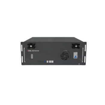
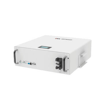
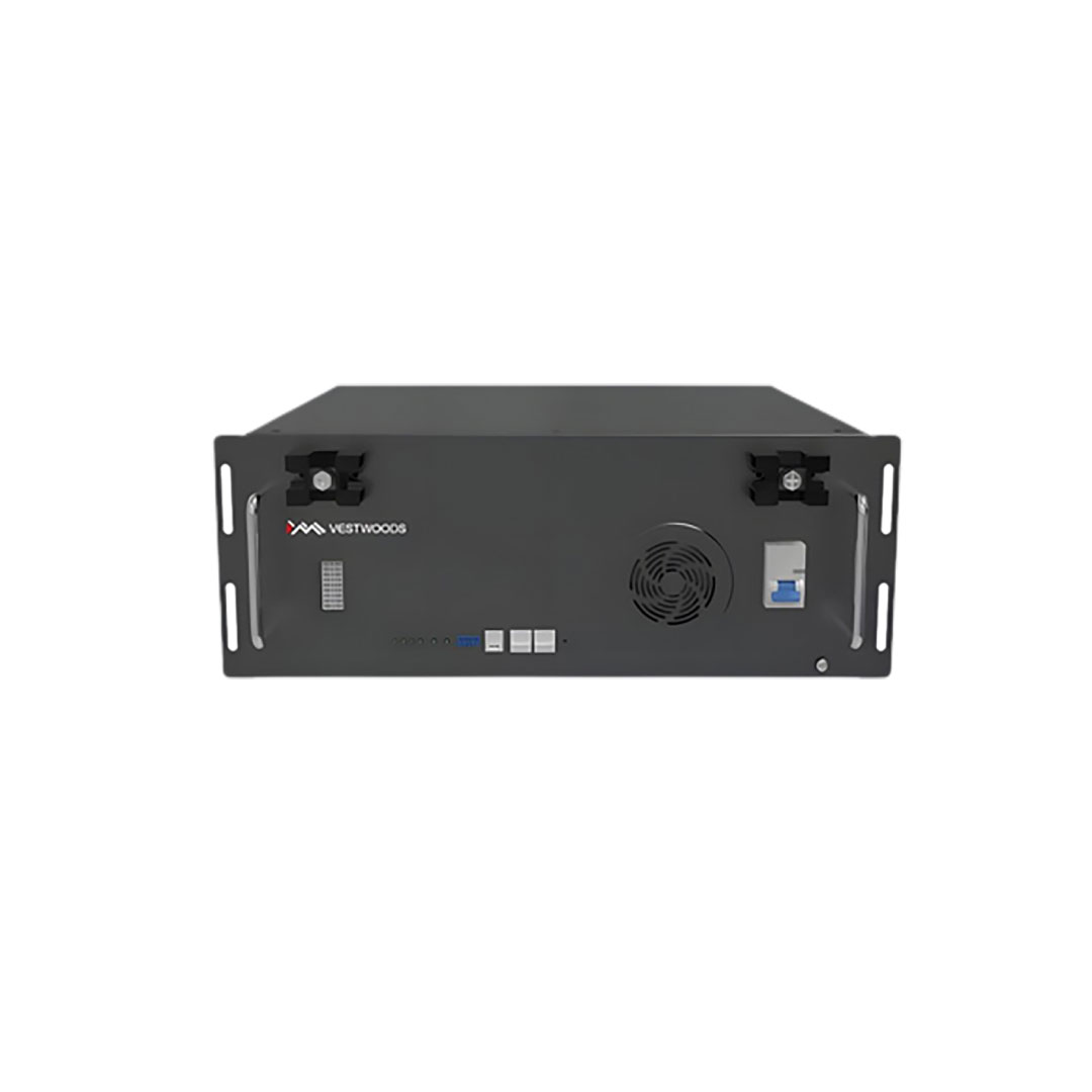
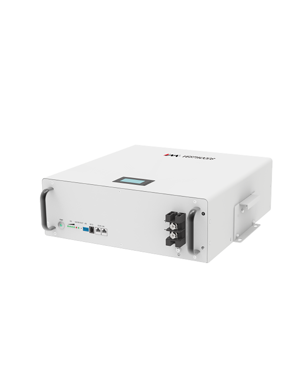
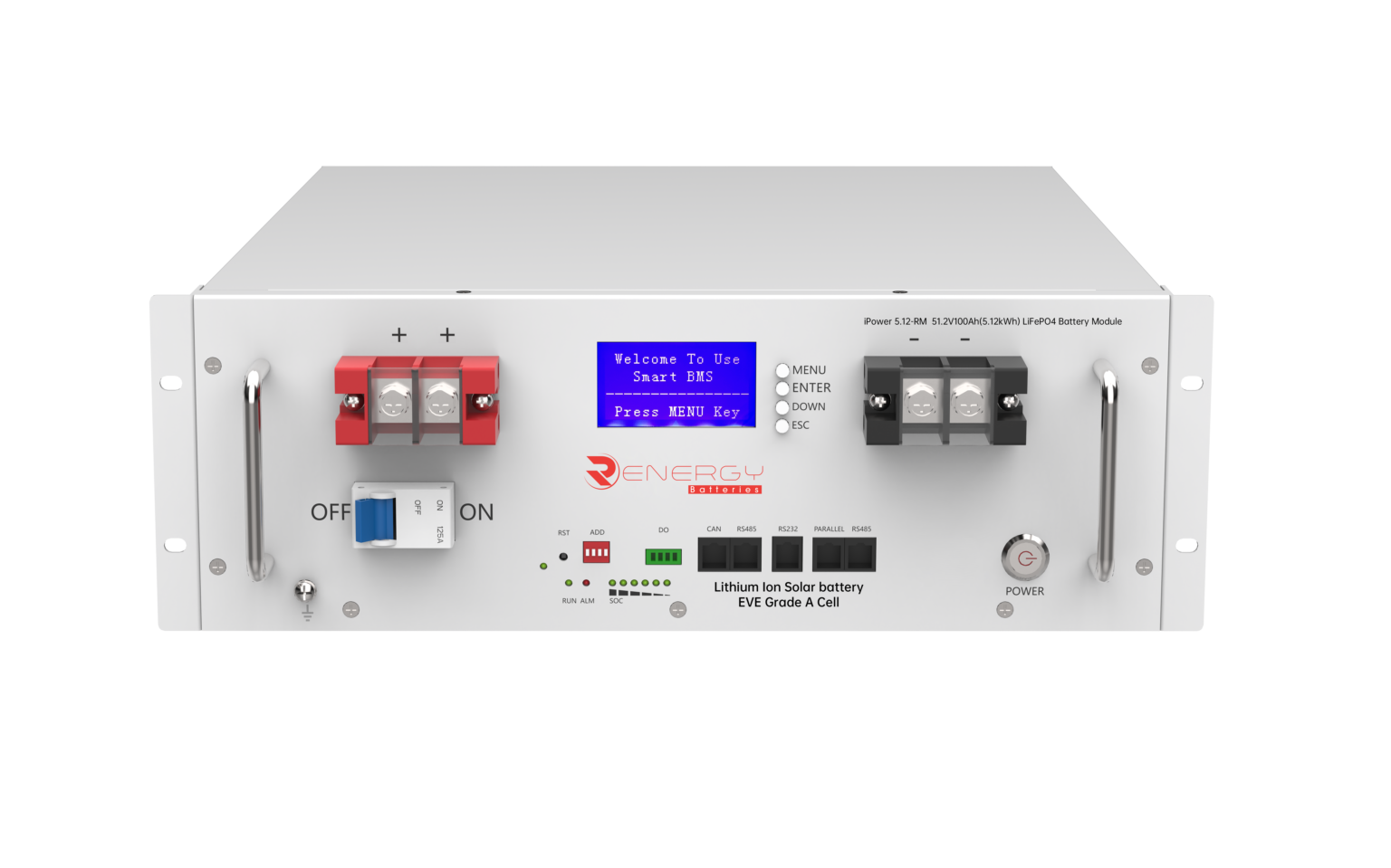
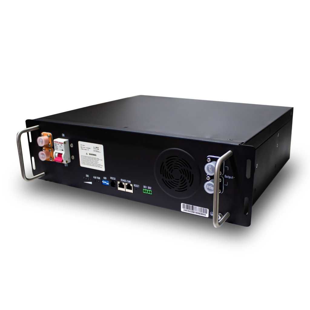
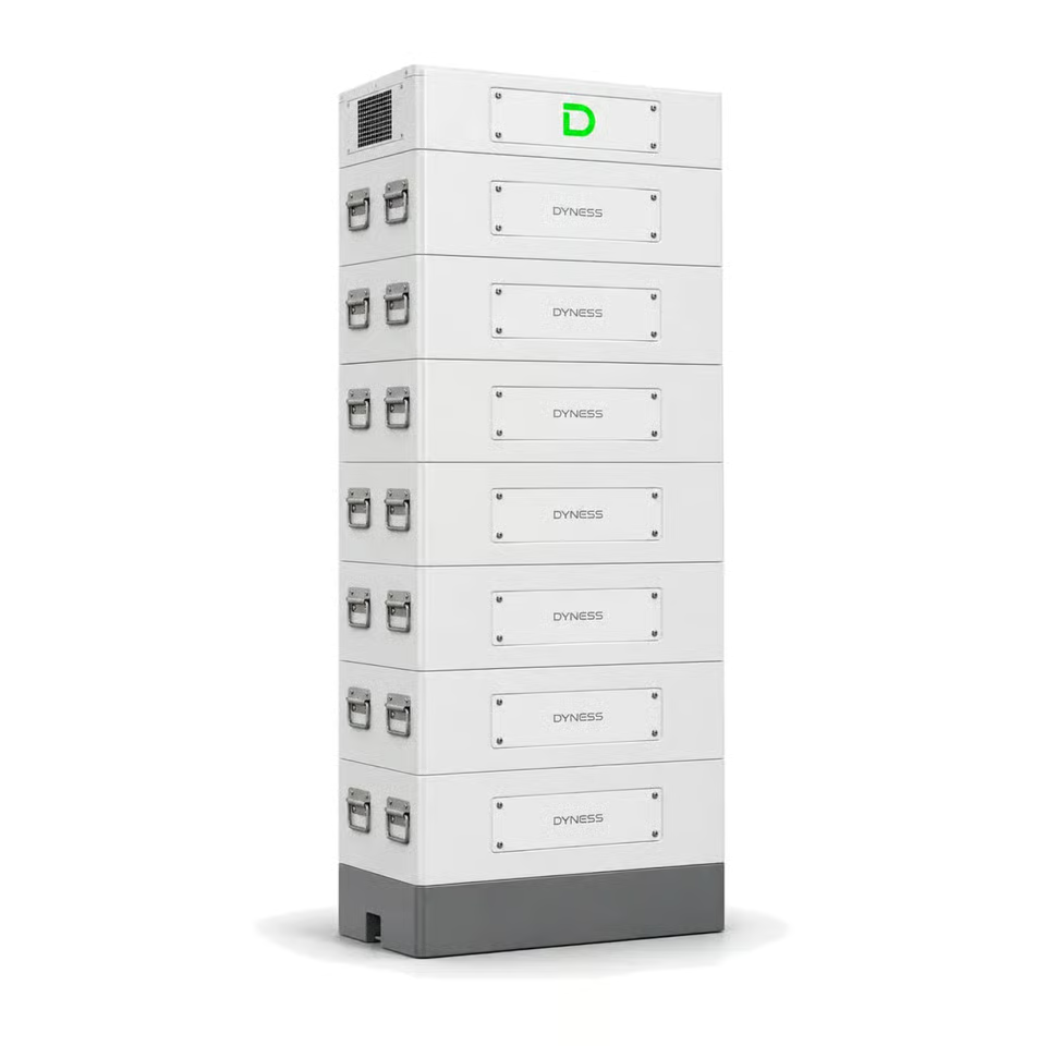
The Dyness SBDU200 controls and isolates a Stack280 cluster. It crowns the column once every module is seated, and it is where the stored energy meets the inverter.
It is not a battery. It holds no cells and stores no energy, so a buyer ordering it in the belief that it adds capacity receives switchgear instead. The energy is in the S51280 modules underneath it.
And it ships with the standard base, not the expansion base. Those are two different parts in two different packages, and confusing them is the most expensive mistake available on this product. The unit arrives with everything a single column needs. A second column needs a separate expansion package, which carries its own base, a cover, and the cables that join the two columns together.
So a one column system is this package plus modules. A two column system is this package, plus modules, plus one expansion package. Ordering the first and assuming it covers the second leaves an installation that cannot be completed.
- One control unit serves the whole cluster, whether it stands as one column or two
- The standard base is included and the column stands on it
- The expansion base belongs to the separate package and is what a second column stands on
- The joining cables, series and parallel, are in that expansion package too
- Wall brackets are included, because the column is secured back to a wall
Dyness SBDU200 Control Unit: Package Contents, Ceiling Height and Column Planning
1. What Is Actually In The Box
This matters more than usual here, because the contents decide whether an installation can be finished on the day it starts.
Supplied with the control unit
- The SBDU200 unit itself, measuring 770 by 425 by 230mm
- The standard base, 770 by 425 by 133mm, which the column stands on
- Two fixing brackets for securing the column back to the wall
- Expansion bolts, two at M6 by 80 and four at M12 by 100
- A terminating resistor for the communication line
- Four M5 by 30 screws and two ring terminals
- An inverter communication cable for CAN, two metres, plugged at both ends
- A second inverter communication cable for RS485, also two metres
- Two power cables to the inverter, 50 square millimetre, just over two metres each
- Manual, warranty card and packing list
Not supplied, and needed only for a second column
- The expansion base, which is a distinct part from the standard one
- The expansion cover, 80mm tall, which closes the top of the second column
- The parallel communication cable linking the two columns
- Two series cables carrying the current between them
- A further pair of wall brackets and their bolts
Two details in that first list repay attention. The terminating resistor is a very small component that commissioning will not proceed without, and it is easily lost between delivery and installation. And the power cables run just over two metres, which sets how far the inverter can sensibly sit from the column before longer cable has to be made up.
2. Technical Specifications
Dyness publishes dimensions and quantities for this unit but does not publish a specification table for it on its own. The table separates what applies to the unit from what applies to the cluster it controls, and shows the unpublished rows as such.
| Parameter | Value | Applies to |
|---|---|---|
| Model | SBDU200 | The unit |
| Function | Control and disconnect unit for one cluster | The unit |
| Dimensions | 770mm wide, 425mm deep, 230mm tall | The unit |
| Base dimensions | 770mm wide, 425mm deep, 133mm tall | Included base |
| Expansion cover height | 80mm | Expansion package |
| Position in column | Fitted last, above the top module | The unit |
| Quantity required | One per cluster, including two column clusters | The unit |
| Mounting | Wall brackets and expansion bolts supplied | The unit |
| Inverter cables supplied | CAN and RS485 at 2m, power at 50mm squared | The unit |
| Unit weight | Not published, and circulating figures disagree | The unit |
| Standalone voltage rating | Not published separately from the cluster | The unit |
| Breaker rating in amperes | Not published | The unit |
| Modules per cluster | 3 to 15 in series | The cluster |
| Modules per column | 8 maximum | The cluster |
| Nominal cluster voltage | 153.6V to 768V, at 51.2V per module | The cluster |
| Operating voltage | 134.4V to 864V | The cluster |
| Energy per cluster | 43kWh to 215.04kWh | The cluster |
| Recommended current | 140A, which is 0.5C | The cluster |
| Maximum continuous current | 200A, which is 0.7C | The cluster |
| Peak current | 280A for 2 minutes at 25C | The cluster |
| Full column height | About 2,208mm at eight modules | The cluster |
| Clearance above the system | 450mm minimum | The cluster |
| Floor to ceiling required | Greater than 2,658mm at eight modules | The cluster |
| Clusters in parallel | Up to 12, reaching 2.58MWh | The system |
| Communication | CAN or RS485, with built in wireless | The system |
| Protection level | IP20, indoor positions only | The system |
| Cooling | Forced air | The system |
| Warranty | 10 years | The system |
About the weight row
The manufacturer’s component table lists this unit with its dimensions and quantity but no weight, and the datasheet gives a weight only for the battery module. Figures published by sellers do exist and they disagree sharply: the unit and base together are quoted both at around 38 kilograms and at around 56 kilograms. A gap of nearly half is not a rounding difference, so neither figure is repeated here. Section five gives the weight that actually governs the installation.
3. Key Points
- A controller and isolator rather than a store, with no cells inside it
- The standard base ships with it and the column stands on that base
- The expansion base is a different part in a separate optional package
- One unit serves the cluster even when that cluster runs as two columns
- It is fitted last, above the topmost module
- A full column of eight modules stands about 2,208mm tall
- The manufacturer requires 450mm of clear space above it
- That makes the floor to ceiling requirement 2,658mm at full height
- Wall brackets are supplied, so the column fixes back to a wall
- Both inverter communication cables and the terminating resistor are included
4. Ceiling Height, Which Decides The Column
This range asks for considerably more headroom than most people expect, and the figure is not the one that applies to the smaller Stack100 range. The manufacturer requires 450 millimetres of clear space above the finished assembly.
The column itself is a 133 millimetre base with every layer above it, modules and control unit alike, at 230.5 millimetres.
| Modules | Energy | Column height | Floor to ceiling needed | Under a 2.4m ceiling |
|---|---|---|---|---|
| 3 | 43.0kWh | 1,055mm | 1,505mm | Fits |
| 4 | 57.3kWh | 1,286mm | 1,736mm | Fits |
| 5 | 71.7kWh | 1,516mm | 1,966mm | Fits |
| 6 | 86.0kWh | 1,747mm | 2,197mm | Fits |
| 7 | 100.4kWh | 1,977mm | 2,427mm | Does not fit |
| 8 | 114.7kWh | 2,208mm | 2,658mm | Does not fit |
Under a standard 2.4 metre ceiling, six modules is the practical limit on one column, not eight. Seven needs 2,427mm and a 2.4 metre room does not have it. Eight needs 2,658mm, which calls for a 2.7 metre room or better.
That turns the plant room into a design input rather than an afterthought. Where the room is a standard height, a design calling for eight modules in one position has to become two columns of four or five, which doubles the floor area required. Where the building has a taller service area, a workshop or a warehouse bay, the full column becomes available and the floor area halves again.
Which range suits a low ceiling
There is a result here that reverses the usual assumption. Comparing full columns, this range is the denser of the two, fitting about 350 kilowatt hours into each square metre of floor against about 334 for the smaller Stack100 range. But a 2.4 metre ceiling cuts this range to six modules while allowing the smaller one fourteen, and at those heights the smaller range delivers about 312 kilowatt hours per square metre against about 263 here.
So in a standard height room the smaller range is roughly a fifth more efficient with floor space, while in a tall room this one is ahead. The ceiling decides, which is why we measure it before recommending a range rather than after.
5. Weight And Floor Loading
The unit’s own weight is not published and the figures in circulation contradict one another, but this changes no engineering decision, because the modules dominate the load entirely.
- Each module weighs 110 kilograms
- A six module column carries 660 kilograms of modules
- A full eight module column carries 880 kilograms of modules
- The footprint is 770 by 425mm, which is about 0.33 square metres
- That concentrates roughly 2,000 to 2,700 kilograms onto each square metre
- The control unit and base add to that but remain a small share of it
A typical office floor is designed around 250 to 300 kilograms per square metre, so these figures sit far above it and ground slabs are the normal answer. The manufacturer’s own datasheet instructs that upper floor installations have the floor assessed before the number of stacks is settled, which is unusual advice to find on a specification sheet and worth taking literally.
6. One Unit, One Cluster, However Many Columns
The arithmetic of how many to order is simpler than it first appears, and it saves money rather than costing it.
| Arrangement | Modules | Control units | Expansion packages |
|---|---|---|---|
| One column | 3 to 8 | 1 | None |
| Two columns, by module count | 9 to 15 | 1 | 1 |
| Two columns, forced by ceiling height | 7 or 8 | 1 | 1 |
| Two separate clusters | Up to 15 each | 1 each | As each layout needs |
| Maximum system | 12 clusters | 12 | As each layout needs |
The third row is the one that catches people out. A design can be driven into two columns by the room rather than by the module count, and when that happens the expansion package becomes necessary even though the module count alone would not have required it. Seven modules in a 2.4 metre room is a two column job.
A cluster is one electrical group under one control unit, and it may be arranged as one column or two. Separate clusters are a different matter and each needs its own unit.
7. Installation Notes
The wall matters
Fixing brackets and masonry bolts are supplied because the column is secured back to a wall rather than standing free. That rules out island positions in the middle of a room and makes the wall construction part of the siting decision, since the fixings need something solid to bite into.
- Choose a wall that will take masonry anchors properly
- Allow the full footprint plus working room on the open sides
- Confirm the 450mm clear space above is genuinely clear of services
- Check for pipework, ducting and light fittings at that height
- Keep the front face reachable for the breaker and the controls
Build order
- Set out, drill and anchor the base before a single module is lifted
- Each module goes on singly and takes four screws before the next follows
- That repeats until the modules and then the control unit are in place
- Wall brackets are fitted and the earthing is made off
- On two column systems the series and parallel cables link the columns
- The terminating resistor goes into the communication chain
Before leaving site
- Confirm module level data is arriving at the inverter and displaying correctly
- Set the charge and discharge limits to the recommended rate
- Verify isolation works and show whoever holds the keys where it is
- Prove dead at the terminals first, since these potentials are lethal
- Leave the module count, column layout and voltage range documented
- Handover performed by people who commission commercial storage regularly
8. Care And Operations
- A dry room throughout, as nothing here is rated against moisture
- Keep the 450mm above the unit clear, since cooling and access both need it
- Keep airflow around the column unobstructed
- Operate the breaker at every service call to confirm it still moves freely
- Inspect the wall fixings and the earthing when the system is serviced
- Check that monitoring and the inverter data feed are both still reporting
- Keep the spare communication parts with the system documentation
9. Do’s And Don’ts
Do
- Measure the ceiling before fixing the module count
- Order an expansion package whenever the design runs to two columns
- Check whether the room, not the capacity, is forcing a second column
- Confirm the standard base is what you have and the expansion base is extra
- Keep the terminating resistor safe between delivery and commissioning
- Choose a wall that will hold masonry anchors
- Assess the floor before committing to an upper storey
Don’t
- Buy it expecting storage, because it holds no cells
- Assume the expansion base is included, because it is not
- Order a second unit for a second column of the same cluster
- Apply the smaller range’s 200mm clearance figure to this one
- Design for eight modules in one stack where the room is 2.4 metres
- Place the column away from a wall it can be fixed to
- Rely on published weights for this part, since they conflict
10. Compatibility
- Stack280 S51280 modules at 51.2 volts and 280 ampere hours
- Clusters of three to fifteen modules, in one column or two
- High voltage inverters covering the voltage the module count reaches
- Solis three phase hybrids from 30 kilowatts upward
- Growatt machines on a high voltage battery platform
- Communication over CAN or RS485, with both cables supplied
- Multi cluster systems of up to twelve clusters
It belongs to the Stack280 range specifically. It is not the same part as the control unit used on the smaller Stack100 range, the two are not interchangeable, and it has no application to 48 volt wall mounted batteries, which manage themselves internally.
11. When To Order One
- A new cluster: one comes with it and belongs on the quotation
- Growing to another cluster: every further cluster takes a unit of its own
- Swapping out a faulty controller: every module carries on unchanged
- Recommissioning: where the original has been lost or damaged
- Buying modules alone: they will not operate without one
- Adding a second column: an expansion package, not another unit
12. Why Buy From Bicity Solar
- Told which base is in the box and which one you still have to buy
- Ceiling measured before a module count is agreed, not after
- Told plainly when the room rather than the capacity is forcing two columns
- Expansion packages quoted upfront where the layout needs them
- One control unit quoted per cluster, never one per column
- Wall construction checked, since the column fixes back to it
- Floor loading assessed at your real module count and storey
- Conflicting published figures flagged rather than repeated
- Inverter distance checked against the cable lengths supplied
- Commissioning that proves the inverter reads every module
- Genuine parts, with paperwork matching the delivery
- Fitted under a current EPRA licence by a commercial storage team
- Warranty claims taken up with the manufacturer by us
- Delivered countrywide, with expansion support later on
Two things to settle before ordering. This package contains the standard base, not the expansion base, so a two column system needs an expansion package as well. And a full column needs 2,658mm from floor to ceiling, which a standard 2.4 metre room does not have.
Send us your ceiling height, the wall you intend to fix to, the storey and the storage you are aiming for. We will tell you how many modules fit a column in that room, whether the layout needs an expansion package, and what the floor will be carrying. Size the system in the Solar Calculator, or send the site details through My Quote.