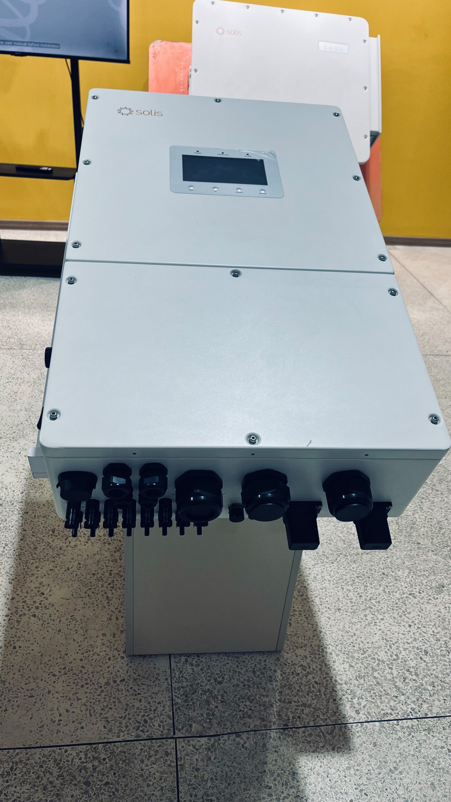
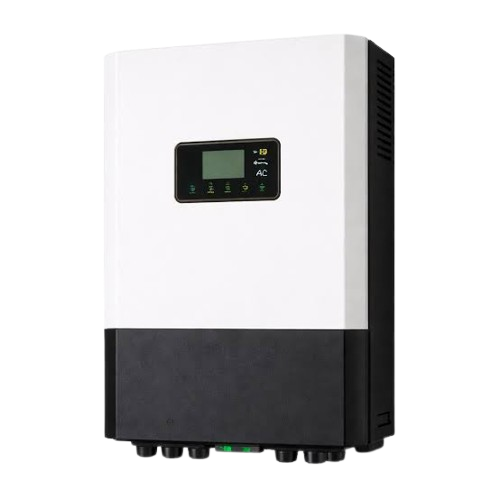
Description
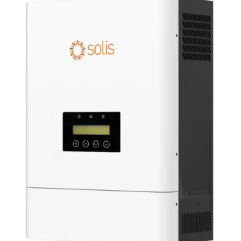
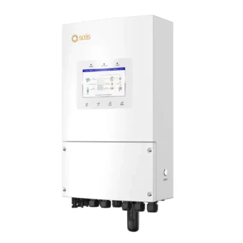
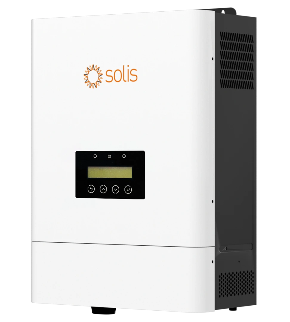
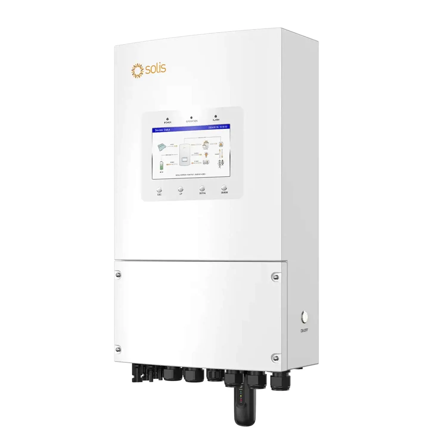
Solis S6-EH1P6K-L-PLUS 6kW 48V Hybrid Inverter: 12kW of Array on a Single Phase Home System
The Solis S6-EH1P6K-L-PLUS delivers 6000W single phase from a 48V battery and carries a 12kW solar array allowance, which is a two to one ratio against its output. It is the size that suits a large Kenyan home or a small commercial premises where 5kW leaves no headroom.
Four characteristics shape how it is specified.
A 12kW array allowance on two strings. Generous, but it comes with a design consequence covered in detail below: reaching it requires long strings, and long strings sit close to the inverter’s voltage ceiling.
135A of battery current. Sized to sustain full 6kW output across the usable discharge range, where 6000W demands 117A at 51.2V and 136A at a deeply discharged 44V.
40A grid charging. Where the mains comes and goes unpredictably, the speed at which a short window of supply refills the bank decides whether you enter the next outage full or half empty.
Under 4ms transfer to backup. A mains cycle lasts 20 milliseconds, so the gap is a fifth of one cycle, shorter than the hold up time of effectively any switched mode power supply. Computers, tills, recorders and network equipment carry on without registering that the grid failed.
Complete Technical Specifications Matrix
Solar PV Input Parameters
| Parameter | Value |
|---|---|
| Recommended maximum PV array size | 12kW |
| Maximum usable PV input power | 9.6kW |
| Maximum input voltage | 500V |
| Rated voltage | 330V |
| Start-up voltage | 90V |
| MPPT voltage range | 90V to 435V |
| Maximum input current | 16A per tracker |
| Maximum short circuit current | 20A per tracker |
| MPP trackers and strings | 2 trackers, 2 strings |
Two separate PV figures apply. The 12kW recommended array size is how much panel may be installed. The 9.6kW usable input is how much the inverter converts at any instant. The gap exists because a 12kW array rarely produces 12kW: heat, dust, haze and panel angle all reduce real output, and cell temperature on a Kenyan roof at midday costs ten percent or more against the standard test rating on its own.
Array Design: Why This Model Needs Long Strings
This is the specification detail that most affects how the system is built, and it follows from a fact that is easy to miss.
The 6kW model uses the same DC hardware as the 5kW in this series: two trackers, 16A each, one string per tracker. Two strings at 16A is 32A of total input current, whatever the array allowance says.
Power is voltage multiplied by current, so with current fixed at 32A the only route to a larger array is higher string voltage. That means more panels in series.
| Panels per string | Operating voltage | Array total | Open circuit on a cold dawn | Against a 500V ceiling |
|---|---|---|---|---|
| 6 x 620W | Around 252V | 7.5kW | Around 330V | Ample margin |
| 7 x 620W | Around 294V | 8.7kW | Around 385V | Comfortable |
| 8 x 620W | Around 336V | 9.9kW | Around 440V | Sensible maximum |
| 9 x 620W | Around 378V | 11.2kW | Around 495V | At the ceiling, verify panel data |
Eight panels per string, sixteen in total, is the configuration that suits most installations. It reaches 9.9kW, which matches the 9.6kW the inverter can actually convert, and leaves roughly 60V of margin below the ceiling on a cold morning.
Nine per string reaches 11.2kW and approaches the full allowance, but sits within a few volts of the limit once panels are cold. That configuration is viable only when the specific panels’ open circuit voltage and temperature coefficient have been checked rather than assumed.
The practical conclusion: the 12kW allowance is reachable on paper but the usable design point is nearer 10kW, and the array should be built from fewer, higher wattage panels in long strings rather than many smaller ones. Smaller panels produce lower string voltage for the same panel count, which caps the array well below what the inverter could take.
AC Output and Backup Power Capacities
| Parameter | Value |
|---|---|
| Rated output power | 6kW |
| Maximum apparent output power | 6kVA |
| Operation phase | Live, neutral and earth |
| Rated grid voltage | 220V or 230V |
| Rated grid frequency | 50Hz or 60Hz |
| Rated grid output current | 27.3A at 220V, 26.1A at 230V |
| Power factor | Above 0.99, adjustable 0.8 leading to 0.8 lagging |
| Current distortion | Under 2% |
| Grid input voltage range | 187V to 253V |
| Grid maximum input current | 40A |
| Grid frequency range | 45Hz to 55Hz, 55Hz to 65Hz |
| Backup rated output power | 6kW |
| Backup maximum apparent power | Twice rated power for 10 seconds |
| Backup switch time | Under 4ms |
| Maximum AC passthrough current | 40A |
| Backup voltage distortion at linear load | Under 2% |
The 40A grid input is a meaningful step up. It allows the battery to be charged from mains or a generator at up to around 9kW of input capacity, so a short window of good supply fills the bank considerably faster than on the 5kW model. On sites where the grid is present but unreliable, this is often more valuable than the extra kilowatt of output.
The 187V to 253V acceptance window matters in Kenya, where voltage droops during evening peak at the end of long distribution feeders. Equipment with a narrower window stops drawing from the grid during exactly the hours charging is most wanted.
48V Battery Management and BMS Communication Specifications
| Parameter | Value |
|---|---|
| Battery type | Lithium ion or lead acid |
| Battery voltage range | 40V to 60V |
| Maximum charge and discharge power | 6kW |
| Maximum charge and discharge current | 135A |
| Battery ports and BMS ports | 1 and 1 |
| Communication protocols | CAN or RS485 |
| Charge and discharge scheduling | 6 programmable periods |
135A is matched to full output, with little spare. Delivering 6kW draws 117A at 51.2V, 125A at 48V and 136A as the bank approaches 44V. The rating covers the range, but the margin at the bottom is slim, and that has a practical consequence worth designing around.
Battery voltage sag directly costs output on this model. A bank that holds its voltage under a 135A load delivers full power to the end of the discharge. A bank that sags, whether because it is undersized for the current, aged, or connected through cable that is too long or too thin, reaches the current ceiling before it reaches full power.
Two things follow. Choose batteries by continuous discharge rating in amps, not only by capacity in kilowatt hours: a single unit rated around 100A continuous will limit this inverter, while two in parallel comfortably carry it. And keep the battery cable short and generously sized, because at 135A every milliohm of resistance becomes voltage lost before the inverter sees it.
Run the BMS link. With it, the inverter works from the battery’s own reported figures: actual charge level, cell temperatures and the limits the pack itself declares. Without it, everything is inferred from terminal voltage, and under a 135A load that voltage tells you very little.
Mechanical, Environmental and Efficiency Ratings
| Parameter | Value |
|---|---|
| Maximum efficiency | Up to 96.2% |
| Protection degree | IP66, indoor or outdoor |
| Operating temperature | -40C to +60C |
| Maximum altitude | 3000m |
| Dimensions | 335 x 560 x 253mm |
| Weight | 23kg |
| Topology | Transformerless |
| Parallel expansion | Up to 48kW |
The unit occupies the same enclosure as the 5kW model in this series, at the same 23kg, so mounting requirements and wall space are identical. The extra kilowatt arrives through the electronics rather than through a bigger box.
Altitude is rated to 3000m, which settles a question that hangs over much of the imported electronics on this market. Thinner air carries heat away less effectively, and a ceiling of 2000m, which some equipment carries, rules out a long list of highland towns. This one covers the whole country. The IP66 enclosure is sealed against dust entirely and against water jets from any direction, making an exterior wall a legitimate home for it, though a position out of direct afternoon sun will always produce more.
Real-World Appliance Compatibility and System Load Limits
Rated output is 6000W continuous, with 12kVA available for ten seconds to start motors.
| Load | Typical draw | On this inverter |
|---|---|---|
| Whole house LED lighting | 30W to 80W | Yes |
| Fridge and chest freezer together | 200W to 400W running | Yes, surge amply covered |
| Home office, several computers and monitors | 300W to 600W | Yes |
| Washing machine, full cycle with heating | 300W to 2000W | Yes |
| Borehole pump, 1hp | 750W running, around 3000W starting | Yes |
| Borehole pump, 2hp | 1500W running, around 6000W starting | Yes, within the 12kVA surge |
| Air conditioner, 1.5hp | Around 1100W running | Yes |
| Microwave | 800W to 1500W | Yes |
| Electric kettle | 1500W to 2200W | Yes |
| Clothes iron | 1000W to 2000W | Yes |
| Instant shower | 3000W to 5500W | Yes alone, not alongside other heavy loads |
| Electric cooker with oven | 3000W to 8000W | Smaller models yes, full ranges no |
| Kettle, iron and shower together | Above 6000W combined | No, this is the ceiling |
The practical difference between this and a 5kW unit is headroom rather than capability. Both run a Kenyan household. At 6kW the combinations that would have tripped a smaller inverter, an instant shower while the kettle boils, or a two horsepower pump starting while the iron is on, stay inside the rating. For a larger home, or one where several people use heavy appliances without coordinating, that headroom is the reason to choose it.
Operational Modes and Smart Energy Management
On-Grid, Off-Grid and Self-Consumption Configurations
Self consumption serves the load from solar first, charges the battery with the surplus, and draws from the grid only for what remains. It is the default and the right mode for most Kenyan installations, since it reduces what you buy without requiring any export arrangement.
Backup operation engages the instant mains disappears, feeding the protected circuits from stored energy and whatever the array is producing, with a gap short enough that connected equipment never registers it. Sites with no utility connection at all can run the inverter in this mode permanently.
Grid charging fills the battery from mains at up to 40A within the 187V to 253V window. On this model that is the fastest route to a full bank, and worth configuring deliberately where supply is intermittent.
Peak Shaving and Time-of-Use Programming
Six separately configurable charge and discharge windows across the day drive both peak shaving and time of use operation.
Peak shaving holds down the highest figure the meter ever records, by meeting the busiest hours from stored energy and the array instead of from the utility. On any connection where a demand charge or a capacity limit applies, this is where the system pays for itself.
Time of use programming charges the battery during hours when supply is reliable and reserves it for hours when outages are likely. On a site with predictable evening load shedding, scheduling a full charge beforehand turns an outage into a non event.
The 40A grid input makes this scheduling more effective here than on smaller models, because a shorter window of supply is enough to complete a bulk charge.
Generator Integration and Automatic Signal Control
The inverter accepts a generator on the AC input within the same 187V to 253V window as the grid, which extends backup through outages longer than the battery alone covers.
With 40A of charging available, a running generator is doing two jobs: carrying the current load and filling the battery behind it. Forty minutes of noise can therefore buy an entire quiet evening. Setting a charge window to coincide with the generator schedule is what makes the fuel count, rather than letting it serve only whatever happens to be switched on.
Automatic generator starting requires the generator to have a compatible remote start input and the control wiring to be installed. Many smaller generators sold in Kenya are manual start only, so confirm this before assuming unattended operation.
Installation, Cable Sizing and Protection Guidelines
Recommended AC and DC Circuit Breakers and Cable Cross Sections
Derived from the datasheet currents, rating each protective device at or above 1.25 times the continuous current and taking the next standard size. These are a design starting point, and an installer should confirm them against actual run lengths, ambient temperature and local regulation.
| Circuit | Design current | Protective device | Cable, short run |
|---|---|---|---|
| PV string, per tracker | 16A, 20A short circuit | 20A DC, rated above 500V | 4mm² double insulated solar cable |
| Battery to inverter | 135A, rising as voltage falls | 200A DC | 70mm², or 50mm² over a very short run |
| AC output to loads | 27.3A | 40A, 2 pole, Type C | 10mm² |
| AC input from grid | 40A | 50A, 2 pole | 10mm² |
| Backup output passthrough | 40A | 50A, 2 pole | 10mm² |
The battery circuit is substantially heavier than on the 5kW model, moving from 35mm² to 70mm², and this is the item most often carried over unchanged when someone upgrades. Cable sized for 112A will run hot at 135A, and the voltage it loses is output the inverter never delivers. Budget for the heavier cable, correctly crimped lugs and a 200A DC device from the start.
The voltage rating on DC protection matters as much as the amp rating. Eight 620W panels in series reach roughly 440V open circuit once the glass is cold. Ask a 250V DC device to break that circuit and it cannot extinguish the arc, whatever number is printed on its current rating. Everything on the DC side here needs to be rated beyond 500V.
Combiner Box and Built-in Safety Protections
| Protection | Status |
|---|---|
| Integrated PV switch | Yes |
| DC reverse polarity protection | Yes |
| Surge protection | Yes |
| Output over current protection | Yes |
| Residual current detection | Yes |
| Insulation resistance monitoring | Yes |
| Anti islanding protection | Yes |
| Integrated AFCI 2.0 | Optional |
AFCI 2.0 is an option, not a fitted default. The feature watches for the electrical signature of an arc forming at a deteriorating DC joint, well before heat becomes fire. It matters more here than on the smaller models, because the long strings this inverter is designed around mean more connectors in the circuit and more voltage sitting across each one. Check whether your unit has it.
On an array this size, a combiner box is worth the line item. It gives an isolation point up at the roof rather than only at the inverter, puts surge protection near where surges actually enter, and turns a sprawl of string cables into one controlled run back to the building.
Built in surge protection is not lightning protection. What the inverter contains is designed to clamp the spikes that travel down a wire. Energy from a nearby strike is a different order of magnitude. Across the Lake Victoria basin, the highlands, and anywhere the long rains bring regular storms, external arrestors and a properly executed earth remain part of the specification.
Lithium Battery Compatibility, CAN Bus and RS485 Protocols
Communication runs over either CAN or RS485, and the approved battery register for this series extends past a hundred manufacturers. The practical value of a list that long is freedom: your storage is not tied to one supplier’s roadmap, and replacing a cell stack in year six is a routine order rather than a hunt for discontinued stock.
Among the approved names that can actually be sourced in this market are Pylontech, Dyness, BYD, Hubble, Freedom Won, Felicitysolar, Vestwoods, LG Energy Solution, BSLBATT, Narada, Taico, Oliter, Shoto, Sunwoda and Soluna.
At 6kW the discharge rating becomes the selection criterion. The inverter can draw 135A, so a battery rated around 100A continuous becomes the limiting component rather than the inverter. Two batteries in parallel, or a single larger unit with a higher continuous rating, is what allows full output to be realised.
Three further points govern whether a given battery works properly. Approval is granted per model rather than per brand, and lists are revised as products change. Protocol and pinout differ between manufacturers, and getting them right is what gives the inverter true state of charge rather than a voltage estimate. And some approvals are specific to a market and to particular inverter firmware.
The manufacturer states plainly that an unapproved pairing risks hardware damage and forfeits cover. We check the match against the current register, build the right communication lead for your specific battery, and set the protocol during commissioning rather than leaving it to chance.
Lead acid batteries are also supported, with no BMS communication, so charging runs on voltage alone and correct charge parameter configuration becomes considerably more important.
Monitoring, Configuration and Smart App Setup
Monitoring runs through the SolisCloud platform, with a datalogger linking the inverter to the network and the app showing solar generation, battery state of charge, household consumption and grid interaction remotely.
Four things are worth completing at commissioning beyond confirming the app connects.
Set the six charge and discharge windows to match how the building actually uses power rather than leaving defaults in place.
Verify the BMS link is communicating, not merely connected. The app should show real battery data including cell level detail. A voltage derived estimate means the link is not working.
Confirm which circuits sit on the backup output. The under 4ms switchover protects only what is physically wired to those terminals, and that is decided at the distribution board rather than in any setting.
Record a baseline. Note production on a clear day shortly after commissioning. Without it, gradual losses from soiling, growing shade or a developing fault are very hard to identify later.
Confirm whether a datalogger ships with the unit or is supplied separately, since this varies by channel.
Certifications, Compliance and Grid Standards
Behind the Solis name is Ginlong Technologies, publicly listed and manufacturing inverters since well before the current wave of entrants. On a product whose warranty may need to be exercised a decade from purchase, the manufacturer’s longevity is itself a specification.
This model is CE marked for Europe, and the series has been certified against the United Kingdom’s G98 and G99 connection codes and holds MCS approval. Passing those is not a formality: they are among the stricter regimes an inverter can be put through, and hardware designed to satisfy them carries that engineering into every market it reaches.
Those requirements show up as hardware. Should the utility drop, anti islanding isolates the inverter so the array cannot push power into lines a technician may be handling. Residual current and insulation resistance are monitored continuously rather than checked at commissioning. Power factor adjusts across 0.8 leading to 0.8 lagging, and distortion stays under 2% on both the grid output and the backup supply at linear load, which is what keeps delicate equipment happy.
For a Kenyan installation, Energy and Petroleum Regulatory Authority requirements apply where the system connects to the national grid, and KEBS standards mark documentation attaches to the consignment rather than to the model. Bicity Solar provides the paperwork for the specific unit supplied, and installs through EPRA certified technicians to EPRA requirements.
Package Contents
In the carton: the unit itself, its mounting plate and fixing hardware, the DC connectors for the solar inputs, and the documentation.
Four items vary by supply channel and are worth confirming on any quotation:
- WiFi datalogger. Required for SolisCloud monitoring and remote configuration.
- Energy meter or current transformer. Needed for consumption monitoring and for peak shaving to work against real demand rather than an estimate.
- Battery communication cable. The item most often assumed. Pinouts differ between battery brands, so a generic lead frequently will not work.
- Printed manual. Increasingly supplied as a download.
We tell you precisely what is in the box for the unit you are buying before money changes hands, and the battery communication lead is made up for your chosen battery rather than left as your problem.
Warranty Terms, Local Technical Support and Registration
How long the cover runs depends on where the unit was sourced and through which channel, so the period and conditions appear in writing on your invoice rather than as a claim on a web page. Three questions get settled on every inverter leaving our premises.
Scope. Whether labour is covered alongside parts, and critically whether a loan unit keeps the site running while a failed one is examined.
Registration. A number of manufacturers grant the headline term only to installations logged with them inside a set window, and quietly apply a shorter default to everything else. Where that applies, we handle the registration.
The claim route. A factory warranty means little without somebody nearby to act on it. Diagnosis, paperwork and distributor negotiation all sit with us, so you are never shipping hardware overseas or emailing a manufacturer yourself.
Technical support extends beyond warranty: commissioning settings, battery protocol configuration, firmware updates and fault diagnosis are handled locally by EPRA certified technicians.
Choosing between 5kW and 6kW comes down to two questions: whether your heavy appliances get used in combination, and whether the roof can carry the longer strings this model is designed around.
Send us the appliances that might run together, the usable roof area and the panels you are considering, and we will confirm the string design against their actual open circuit figures, size the battery against the 135A draw, and say honestly whether the extra kilowatt earns its place. Start a full property assessment with the Solar Calculator, or send your requirements through My Quote for a costed proposal covering inverter, battery, array, protection and installation.