
Description
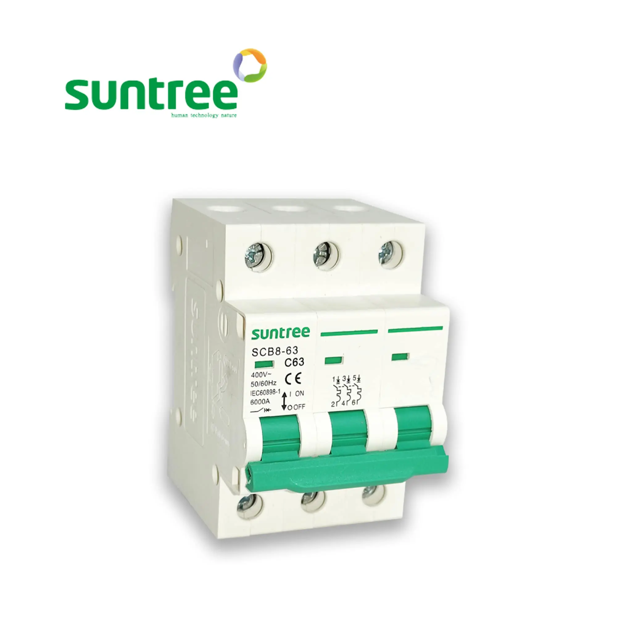
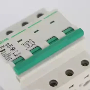
Triple Pole MCB 63A — SCB8-63 3P 400VAC Three Phase Circuit Breaker
The Triple Pole MCB 63A — also searched throughout Kenya as 3 Pole MCB 63A, Three Phase MCB 63A, or 63A 3P circuit breaker — is the standard branch protection device for medium-power balanced three-phase loads. Where the four-pole equivalent switches a neutral conductor alongside the three lines for installations with mixed single-phase outgoing ways, this 3P configuration is purpose-built for the pure three-phase circuit: a three-phase motor without auxiliary single-phase auxiliaries, a balanced three-phase resistive heater bank, a three-phase inverter exporting line-to-line with no neutral routing, or a generator output where the neutral is bonded to the generator frame downstream.
At 63 amperes per pole on a 400V three-phase supply, the breaker handles up to about 43 kVA total — covering the load envelope from 11 kW to 22 kW three-phase induction motors, light-industrial CNC and milling equipment, three-phase MIG and TIG welding plants in fabrication workshops, HVAC chiller compressors in medium commercial premises, and the AC output of three-phase grid-tie or off-grid solar inverters in the 15 kW to 22 kW range when the inverter exports balanced three-phase without a neutral conductor. The C-curve thermal-magnetic trip characteristic and 6 kA breaking capacity match the typical fault profile of branch positions on Kenyan three-phase distribution networks.
What separates the 3P 63A from the 4P 63A variant
A common source of confusion in the Kenyan market is the choice between the triple-pole and four-pole variants of the same nominal current. The difference is in the number of switched conductors, not the trip mechanism or the breaking capacity — both share the same internal architecture per pole, and both ship with the C-curve trip profile and 6 kA fault interrupt rating. The decision turns on what sits downstream:
- Choose the triple-pole device when the load is a balanced three-phase appliance with no neutral conductor routing — induction motors, three-phase resistance heating banks, three-phase MIG welders, three-phase HVAC compressors, and balanced three-phase inverter outputs without neutral export.
- Choose the four-pole device when the downstream installation includes any single-phase outgoing ways, when the three-phase load uses a neutral conductor for control circuits or imbalanced operation, or when the breaker serves as the master switch above a consumer unit feeding mixed three-phase and single-phase circuits.
For the dedicated pure three-phase branch — which describes most industrial and agricultural motor circuits, machine tool feeders, and grid-tie inverter outputs in Kenya — the triple-pole 63A is the technically correct and cost-effective choice. The 3P device typically costs 25 to 35 percent less than its 4P sibling at the same rating, occupies one less DIN rail module, and simplifies the wiring of pure three-phase loads by removing an unnecessary neutral termination.
Why competitor “triple pole” pages don’t help installers
If you have been searching for a 3P 63A MCB across the Kenyan online retail landscape, you have likely encountered a problem: most listings provide minimal technical depth, often reusing the same generic two-sentence description across every pole count and current rating in the seller’s catalogue. Critical questions — what motor sizes does this protect, what cable size matches the rating, how does it coordinate with motor overload relays, what is the actual breaking capacity at 400V — go unanswered. This page sets out the answers in full, backed by IEC 60898-1 specifications, EPRA installation conventions, and real-world Kenyan application context.
Technical Specifications
| Field | Specification |
|---|---|
| Compliance Standard | IEC 60898-1 (household-and-similar fixed installations) |
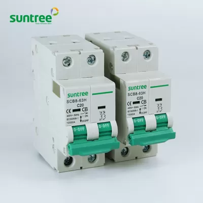
| Reference Catalogue Code | SCB8-63 — 3P 63A configuration |
| Service Voltage Range | 400V AC line-to-line, 230V AC line-to-neutral |
| Frequency Compatibility | 50 Hz and 60 Hz |
| Nominal Current per Pole (In) | 63 amperes continuous |
| Three-Phase Total Capacity | ~43 kVA at balanced loading |
| Magnetic Trip Threshold | 5× to 10× nominal — type C curve |
| Thermal Trip Characteristic | Inverse time, calibrated to IEC 60898-1 curve |
| Short-Circuit Breaking Capacity (Icn) | 6 kA at 400V three-phase |
| Rated Insulation Voltage (Ui) | 500V |
| Rated Impulse Voltage (Uimp) | 4 kV typical |
| Pollution Tolerance | Class 2 — sealed indoor panel |
| Operating Lever Cycles (mechanical) | 20,000 ON–OFF actions |
| Switching Cycles under Rated Load | 4,000 operations minimum |
| Mounting Standard | Snap-on 35mm symmetrical DIN rail |
| DIN Rail Footprint | 3 standard 18mm modules |
| Switched Poles | Three (line conductors only — no neutral) |
| Trip Linkage | Mechanical common-bar — single-pole fault drops all three |
| Terminal Aperture per Pole | Up to 25mm² stranded copper |
| Recommended Feed Conductor | 16mm² copper per phase; 25mm² for runs >15m |
| Ambient Temperature Tolerance | −5°C to +40°C without derating |
| Per-Pole Position Indicator | Mechanical flag visible on front face |
Headline Engineering Features
- Common-trip integrity across all three poles — a fault detected on any one line mechanically operates the other two through an internal coupling bar, preventing single-phasing on motor loads (which would otherwise burn out windings within minutes).
- Three-module compact footprint — half the width of an equivalent moulded-case device, freeing rail space for motor protection relays, contactors, and timer modules in the same panel.
- Type C trip curve calibrated for motor inrush — magnetic threshold at five to ten times nominal absorbs the six-to-seven-times-running starting surge of three-phase induction motors during the two-to-three second startup window without nuisance trip.
- Generous 25mm² terminal capacity — comfortably accepts the 16mm² and 25mm² copper conductors typical of 63A three-phase branches in Kenyan industrial wiring.
- Independent pole status indicators — three separate windows confirm the mechanical position of each pole during isolation, essential for the lockout-tagout safety check before any work on the connected motor or machine.
- V0 flame-rated polymer housing — withstands repeated branch fault clearance under heavy industrial load conditions without softening or distortion.
- Identical depth profile to family siblings — installs flush in panels populated by other SCB8-63 breakers, presenting a clean uniform appearance to inspectors and clients.
- Field-replaceable on energised panels — DIN-rail clip allows rapid swap after upstream isolation, minimising downtime during maintenance windows.
Real Kenyan Installation Applications
- Branch protection for 11 kW, 15 kW, 18.5 kW, and 22 kW three-phase induction motors driving submersible borehole pumps, irrigation pumps, dairy parlour vacuum compressors, and grain elevator drives
- Three-phase CNC machine, lathe, milling machine, and surface grinder feeders in metalwork and fabrication shops
- Industrial three-phase MIG and TIG welding plant in fabrication workshops drawing balanced three-phase supply
- HVAC chiller compressors and condenser units in supermarkets, hotels, restaurants, and clinics
- Three-phase grid-tie solar inverter outputs at 15 kW to 22 kW where the inverter exports balanced line-to-line without neutral
- Three-phase generator output isolators on standby generation sets in commercial and institutional installations
- Motor starter panel mains incomer ahead of the contactor and motor overload relay
- Three-phase ATS panel branch isolators selecting between mains, generator, and solar inverter inputs
- Three-phase resistance heating banks in industrial process equipment and large commercial water heating
- Light-industrial production line three-phase distribution sub-mains feeding multiple machine stations
Installation Notes
Branch protection at the 3P 63A level demands disciplined installation practice. Six points govern the work. First, conductor sizing — each of the three phase conductors should be 16mm² copper minimum on runs up to fifteen metres, increasing to 25mm² on longer runs or where the cable passes through warm voids. Second, phase rotation — confirmed with a phase sequence indicator before any downstream motor is connected, since reverse rotation causes motors to spin backwards and can cause mechanical damage to drives, pumps, and conveyors. Third, terminal torque — each of the six terminations (three supply, three load) tightened to the manufacturer’s specified value with a calibrated torque screwdriver. At sixty-three amperes per pole running continuously, loose terminations heat measurably within hours and degrade contact integrity within weeks. Fourth, no neutral termination required — this is a 3-pole device, so the neutral conductor (if present in the feeding cable for any reason) bypasses the breaker entirely and connects directly to the panel’s neutral bar. Fifth, downstream motor protection — the MCB clears short circuits and gross overloads, but precise motor thermal protection requires a separate overload relay sized to the specific motor full-load amperes. Sixth, environment — mounted inside a panel enclosure with adequate ventilation, away from direct sunlight and rain, with ambient temperatures kept under forty degrees Celsius for sustained operation near nameplate rating.
For installations involving three-phase grid-tie inverters, the MCB sits between the inverter’s AC output terminals and the upstream changeover device or main distribution board. Phase rotation must match the supply at the grid synchronisation point, or the inverter will fail to clock onto the supply and report a phase-error fault. Confirm rotation with a rotation tester after the breaker but before energising the inverter for the first time.
Designing a motor panel, welding workshop, or three-phase solar AC distribution?
Get a complete branch-by-branch protection schedule with motor overload relays, contactors, and cable specifications — start with our Solar Calculator for system-wide sizing, or describe your three-phase loads through My Quote for a complete panel build-up.
