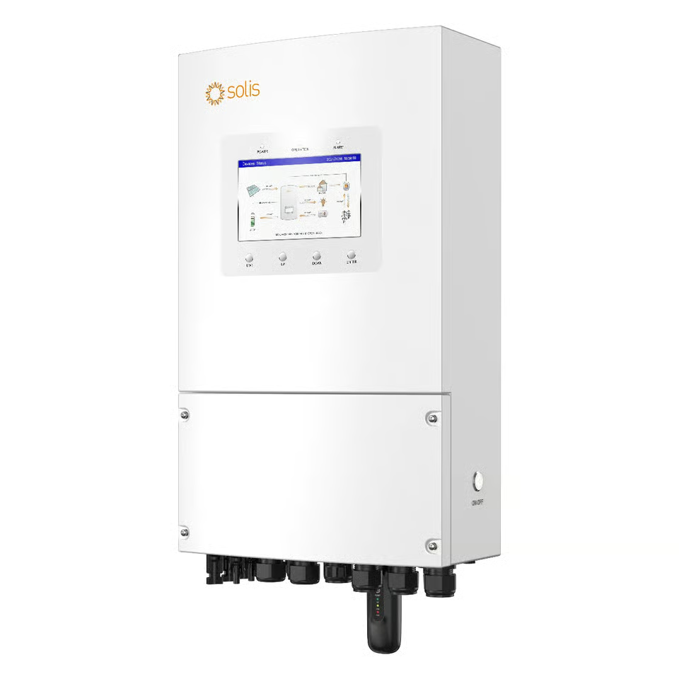
Description
Solis S6-EH1P10K-L-PLUS 10kW 48V Hybrid Inverter: Four Strings and a 20kW Array on Single Phase
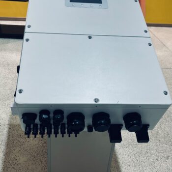
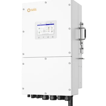
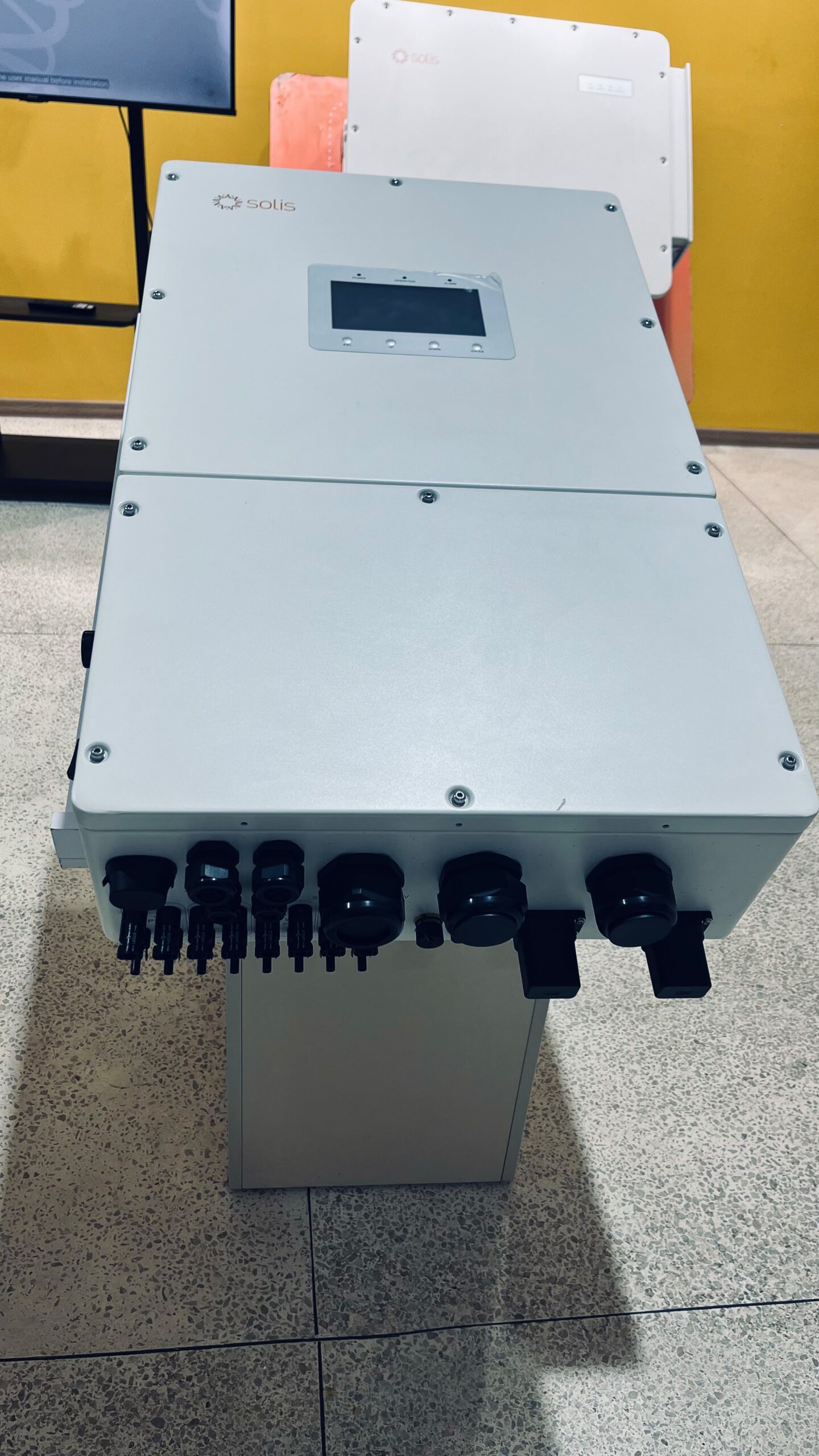
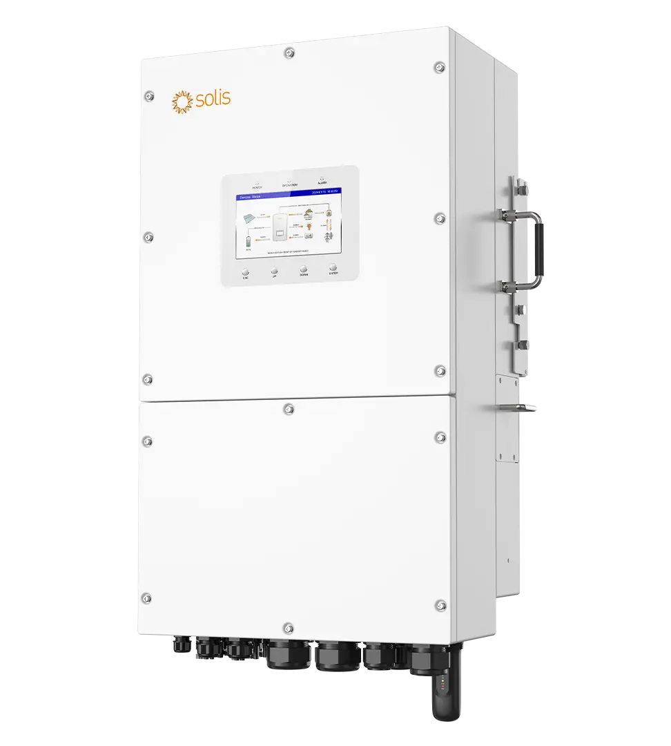
The Solis S6-EH1P10K-L-PLUS produces 10000W from a single phase supply and a 48V battery, and accepts a solar array of up to 20kW. It sits at the top of the low voltage PLUS range and suits a large residence, a guest house, a clinic or a workshop where the load profile has outgrown anything smaller.
What separates it from the rest of the range is the front end rather than the output figure.
Four PV strings instead of two. The smaller units in this family give you one string per tracker. This one gives two, across a pair of trackers rated 42A each, for 84A of total input capacity. Roof layouts that would have been impossible lower down the range become straightforward.
A 20kW array allowance, reached without extreme string lengths. Because the capacity arrives through additional strings, eight panels in each of four strings reaches nearly 20kW while string voltage stays modest.
A published full load voltage floor. The manual states that everything the inverter is rated for is available between 186V and 435V, a figure most listings omit, and it sets a minimum sensible string length rather than only a maximum.
210A of battery current. Enough to deliver rated output through most of a discharge, with the qualification covered below.
65A of grid charging. Substantial, and it brings a requirement most listings never mention: your incoming electrical service has to be able to supply it. That question is dealt with early on this page because it decides whether the inverter can be installed at all.
Complete Technical Specifications Matrix
Solar PV Input Parameters
| Parameter | Value |
|---|---|
| Recommended maximum PV array size | 20kW |
| Maximum usable PV input power | 16kW |
| Maximum input voltage | 500V |
| Rated voltage | 330V |
| Start-up voltage | 90V |
| MPPT voltage range | 90V to 435V |
| Full load MPPT voltage range | 186V to 435V |
| Maximum input current | 42A per tracker |
| Maximum short circuit current | 48A per tracker |
| MPP trackers and strings | 2 trackers, 4 strings |
Array capacity and usable input are separate numbers. Twenty kilowatts is what may be fitted to the roof; sixteen is what the electronics will convert at any given instant, which is the 1.6 ratio of solar to inverter capacity the manufacturer states the unit supports. The margin between them exists because panels in service do not reach their laboratory rating, and on an equatorial roof the dominant reason is cell temperature, which alone removes something in the region of a tenth of nameplate output during the hottest part of the day.
Array Design: Two Voltage Figures, Not One
Most listings quote a single MPPT range for this inverter, 90V to 435V, and leave it there. The manufacturer’s manual publishes a second range that matters more: full output is available between 186V and 435V.
Those two figures do different jobs. Ninety volts is where the trackers begin to operate, which governs how early in the morning the array starts contributing. One hundred and eighty six volts is where the inverter can deliver everything it is rated for. A string sitting between the two will produce power, but not full power.
That sets a floor on string length, and it is the detail most likely to be missed. Panel voltage falls as cells heat, by roughly an eighth on a hot roof at midday, which is exactly when the array ought to be delivering most.
The second constraint is the four string architecture itself. Lower down this range each tracker takes one string, giving 32A of input in total, so a larger array can only be built by making strings longer and pushing them toward the voltage ceiling. Here two strings share each tracker and the trackers carry 42A apiece, so 84A is available and capacity comes from adding strings instead.
Working between those limits gives a usable envelope.
| Layout | Operating voltage, moderate | Operating voltage, hot roof | Open circuit when cold | Array total | Assessment |
|---|---|---|---|---|---|
| 5 x 620W in each of 4 strings | Around 210V | Around 185V | Around 275V | 12.4kW | Sits on the full load boundary when hot |
| 6 x 620W in each of 4 strings | Around 252V | Around 222V | Around 330V | 14.9kW | Practical minimum, clear of the floor |
| 7 x 620W in each of 4 strings | Around 294V | Around 259V | Around 385V | 17.4kW | Comfortable at both ends |
| 8 x 620W in each of 4 strings | Around 336V | Around 296V | Around 440V | 19.8kW | Fills the allowance, margin at both limits |
Six to eight panels per string is the envelope. Six keeps the string clear of the full load boundary in the heat of the day. Eight reaches 19.8kW from thirty two panels while open circuit voltage stays around 440V on a cold morning, sixty volts below the 500V limit. Five panel strings are the arrangement to avoid: the array will generate, but on the hottest afternoons the string voltage arrives at the point where the inverter can no longer give everything it has.
Within that envelope the flexibility is real. Four strings can be spread across four separate roof planes, run in pairs across two, or combined however the building allows, and each string is independently short enough to fit a modest roof face. That is what a two string inverter cannot do at this capacity.
Figures above are worked from a 620W panel of common current specification and are illustrative. Final string design belongs to the panel actually selected, since open circuit voltage and temperature coefficient differ between models and both feed directly into these limits.
AC Output and Backup Power Capacities
| Parameter | Value |
|---|---|
| Rated output power | 10kW |
| Maximum apparent output power | 10kVA |
| Operation phase | Live, neutral and earth |
| Rated grid voltage | 220V or 230V |
| Rated grid frequency | 50Hz or 60Hz |
| Rated grid output current | 45.5A at 220V, 43.5A at 230V |
| Power factor | Above 0.99, adjustable 0.8 leading to 0.8 lagging |
| Current distortion | Under 3% |
| Grid input voltage range | 187V to 253V |
| Grid maximum input current | 65A |
| Backup rated output power | 10kW |
| Backup maximum apparent power | Twice rated power for 10 seconds |
| Backup switch time | Under 4ms per the model manual, under 10ms in series literature |
| Backup rated output current | 45.5A at 220V, 43.5A at 230V |
| Maximum AC passthrough current | 65A |
| Backup voltage distortion at linear load | Under 2% |
Supply Capacity: The Question to Settle First
Two figures on that table have consequences beyond the inverter itself.
Charging draws up to 65A. Add whatever the building is consuming at the same moment and the total can approach or exceed the capacity of an ordinary single phase domestic service. Many Kenyan homes are fed through a main rated well below that. Where the service cannot carry it, the options are to upgrade the supply, to cap the charge current in the inverter settings, or to lean on solar for charging and treat the grid as a secondary route.
Output reaches 45.5A. That calls for a 63A protective device and 16mm squared conductors on the AC side, which is a heavier circuit than a good many domestic consumer units were built around. The distribution board usually needs attention as part of the installation rather than afterwards.
Neither point is a fault in the equipment. Both are the consequence of putting 10kW through a single phase, and both are far cheaper to resolve during design than during commissioning.
Backup Switching and a Note on Published Figures
The manual for this model specifies transfer to backup in under 4 milliseconds, the same figure carried by the smaller units in the family. Solis’s range level literature quotes under 10 milliseconds as a general figure covering the wider series. We publish both because they differ, and the model specific manual is the one that describes this unit.
Either figure is quick enough for the equipment in a Kenyan home or office. Four milliseconds is shorter than the period most switched mode power supplies can bridge from their own internal reserves, which is why computers, televisions, routers and modern electronics carry straight through a utility failure without restarting. Ten milliseconds, half a mains cycle, still falls inside the ride through capability of most modern equipment.
What this means in practice is that the inverter can sit on the whole house rather than on a separate protected circuit, and the household learns about an interruption from the neighbours rather than from its own lights.
48V Battery Management and BMS Communication Specifications
| Parameter | Value |
|---|---|
| Battery type | Lithium ion or lead acid |
| Battery voltage range | 40V to 60V |
| Maximum charge and discharge power | 10kW |
| Maximum charge and discharge current | 210A |
| Battery ports and BMS ports | 1 and 1 |
| Communication protocols | CAN or RS485 |
| Charge and discharge scheduling | 6 programmable periods |
Drawing 10kW from a bank sitting at 51.2V calls for about 195A, which the 210A ceiling covers comfortably. At 48V the requirement rises to roughly 208A, still within reach. Towards the end of a deep discharge, around 44V, full output would want approximately 227A, which is beyond the rating, so available power tapers as the bank empties.
This behaviour is normal on low voltage architectures and rarely noticed, because a bank that low is usually being recharged rather than asked for maximum output. It does mean the battery should be chosen on its sustained current capability rather than on stored energy alone. Supplying 210A continuously calls for three units of the common 100A class, or two of the larger 314Ah units carrying a higher continuous rating, which produces a bank somewhere between fifteen and thirty two kilowatt hours.
A communication link over CAN or RS485 lets the inverter work from the pack’s reported charge level, cell temperatures and declared limits. Operating on terminal voltage alone, while possible, gives a far coarser picture at these currents.
Mechanical, Environmental and Efficiency Ratings
| Parameter | Value |
|---|---|
| Maximum efficiency | 96.2% |
| European weighted efficiency | 96.1% |
| Battery charged from PV | Up to 95.3% |
| Battery charged from AC | Up to 93.9% |
| Battery discharged to AC | Up to 93.8% |
| Topology | Non isolated on the PV side, isolated on the battery side |
| Cooling | Fan cooling |
| Protection degree | IP66, indoor or outdoor |
| Protection class | I |
| Overvoltage category | II on PV and battery, III on mains, backup and generator |
| Operating temperature | -40C to +60C |
| Maximum altitude | 3000m |
| Dimensions | 335 x 560 x 253mm |
| Weight | 23.8kg |
| Parallel expansion | Up to 6 units, giving 60kW |
A European weighted figure of 96.1% against a 96.2% peak is unusually tight, and it is the more useful of the two. The weighted measurement samples performance across the range of loads an inverter actually sees rather than at its single most favourable point, so a narrow gap indicates the unit holds its efficiency whether it is lightly loaded at breakfast or working hard at midday.
The separate round trip figures are worth reading as well. Storing solar energy and returning it later costs roughly ten percent in total, which is a reason to use generation directly where the timing allows rather than cycling everything through the battery.
Cooling is by fan rather than passive convection, which is what allows a 10kW unit to stay within a 23.8kg enclosure. Fans move air and make a modest amount of noise under load, so a position adjoining a bedroom wall is worth reconsidering at the design stage.
Altitude is rated to 3000m, comfortably covering every town in Kenya including the highland locations that sit above the 2000m ceiling some imported equipment carries. The operating range runs from -40C to +60C, far wider than anywhere in this market requires. The IP66 enclosure is sealed completely against dust and withstands water jets from any direction, so an exterior wall is a legitimate location, though a shaded one will always perform better than a wall in full afternoon sun.
Real-World Appliance Compatibility and System Load Limits
At 10kW the question stops being which appliances are possible and becomes how many can run at once. Individually, nothing in a Kenyan home troubles this inverter.
| Simultaneous combination | Approximate total | Headroom remaining |
|---|---|---|
| Lighting, refrigeration, electronics, internet | Around 600W | Over 9kW |
| The above plus a 2hp borehole pump running | Around 2.1kW | Nearly 8kW |
| The above plus two air conditioners | Around 4.3kW | Over 5kW |
| The above plus a kettle and a microwave | Around 7.5kW | Around 2.5kW |
| The above plus an instant shower | Around 12kW | Exceeds the rating |
| Instant shower, kettle, iron and oven together | Around 11kW | Exceeds the rating |
Roughly speaking, this inverter carries an entire household with its heavy appliances in use, and only reaches its limit when several heat producing devices are deliberately run at the same moment. Two showers simultaneously, or a shower alongside a full cooker and a kettle, will find the ceiling. Nothing short of that will.
Motor starting is handled by twenty kilovolt amperes of surge for ten seconds, which covers borehole pumps, compressors, workshop machinery and air conditioning startup with a very wide margin.
Operational Modes and Smart Energy Management
On-Grid, Off-Grid and Self-Consumption Configurations
Self consumption directs generation to whatever the building is using, banks the remainder, and buys from the utility only to cover any shortfall. For almost every installation in this market it is the correct default, since it lowers the bill without depending on an export agreement.
Backup operation engages when the utility fails, running the protected circuits from stored energy and live generation. A property with no grid connection whatsoever can be configured to run this way permanently.
Grid charging replenishes the bank from the mains within the 187V to 253V acceptance range. At up to 65A this is the quickest route to a full battery in the range, subject to the service capacity question raised earlier.
Peak Shaving and Time-of-Use Programming
Six independently configurable periods govern when the battery charges and when it discharges.
Peak shaving suppresses the highest demand figure the meter ever sees, by covering the busiest hours from the battery and the array rather than from the utility. Any connection carrying a demand charge or a capacity limit benefits directly, and at 10kW the amount of demand that can be shifted is considerable.
Time of use scheduling fills the bank when supply is dependable and holds it for the hours when it is not. Where evening interruptions follow a pattern, a charge window placed ahead of them means the household passes through without noticing.
A system of this size makes the scheduling worth more than it would be on a smaller unit, simply because there is more energy moving through it each day. Twenty minutes spent matching the windows to the building’s actual rhythm is repaid continuously.
Generator Integration and Automatic Signal Control
A generator connects to the AC input and is accepted across the same voltage window as the utility supply, extending backup through interruptions that outlast the battery.
The 65A charging capability changes what a generator run achieves. Rather than merely carrying the load while it runs, the machine simultaneously refills the bank at high rate, so a short period of operation can underwrite an entire evening of silence afterwards. Aligning a scheduled charge window with the generator’s running hours is what turns diesel into stored energy instead of into whatever happens to be switched on.
Generators should be sized against the combined figure, since the inverter will attempt to charge at full rate alongside serving the building. Unattended starting additionally requires the generator to offer a remote start facility and the control wiring to be run, which many smaller units sold locally do not provide.
Installation, Cable Sizing and Protection Guidelines
Recommended AC and DC Circuit Breakers and Cable Cross Sections
Calculated from the rated currents, with each protective device set at or above 1.25 times the continuous figure and rounded to the next standard size. Treat these as the design starting point; final selection belongs to the installer working from actual run lengths, grouping, ambient temperature and prevailing regulation.
| Circuit | Design current | Protective device | Cable, short run |
|---|---|---|---|
| PV, per string | 21A, being the per input share of the 42A tracker rating | 32A DC, rated beyond 500V | 4mm² double insulated solar cable |
| Battery to inverter | 210A, rising as voltage falls | 315A DC | 95mm² |
| AC output to loads | 45.5A | 63A, 2 pole, Type C | 16mm² |
| AC input from grid | 65A | 100A, 2 pole | 25mm² |
| Backup output passthrough | 65A | 100A, 2 pole | 25mm² |
The battery circuit deserves particular respect. At 210A the conductors are substantial, the lugs must be crimped with the correct tooling rather than improvised, and every termination needs tightening to the stated torque. Resistance anywhere in that path turns into heat and into voltage that never arrives at the inverter, and at this current level a poor joint is a safety matter rather than an efficiency one. Keep the run short, ideally under two metres.
On the DC side, voltage rating matters as much as current rating. Eight panels in series approach 440V once the glass has cooled overnight, and a device sold as 250V DC cannot safely break that circuit no matter what its ampere figure says. Everything protecting the array should be rated beyond 500V.
Combiner Box and Built-in Safety Protections
| Protection | Status |
|---|---|
| Integrated PV switch | Yes |
| DC reverse polarity protection | Yes |
| Surge protection | Yes |
| Output over current protection | Yes |
| Residual current detection | Yes |
| Insulation resistance monitoring | Yes |
| Anti islanding protection | Yes |
| Integrated AFCI 2.0 | Optional |
Arc fault detection is offered rather than fitted as standard, and on a four string array it is the option most worth taking. More strings mean more connectors, more terminations and more opportunities for a joint to loosen or corrode over a decade on a hot roof. The detection circuitry recognises the electrical signature of an arc forming and shuts the input down before heat becomes fire.
With four strings arriving from potentially several roof planes, a combiner enclosure earns its place. It provides isolation up at the array rather than only at the inverter, a mounting point for surge protection close to where surges enter the system, and a disciplined transition from several string cables into one controlled run.
The surge protection built into the inverter is intended for transients that travel along conductors. A nearby lightning strike delivers energy at a wholly different scale. Storm prone districts, and the lakeside counties in particular, call for external arrestors and a properly constructed earth as part of a complete specification rather than as an upgrade.
Lithium Battery Compatibility, CAN Bus and RS485 Protocols
Battery communication runs over CAN or RS485, and the approved register for this series covers well beyond a hundred manufacturers. A list of that length is worth something practical: storage choice stays open, and replacing a pack several years from now is an ordinary transaction rather than a search for obsolete stock.
Among the approved packs readily available through Kenyan channels are Dyness, Pylontech, Hubble, Vestwoods and Felicitysolar. The register additionally carries BYD, Freedom Won, LG Energy Solution, Narada, BSLBATT, Shoto, Soluna, Sunwoda, Oliter and Taico, which arrive on project order.
At 210A the battery’s sustained current rating becomes the governing specification rather than its capacity. A single pack rated around 100A will restrict this inverter well below its potential, so the bank needs building accordingly.
Approval attaches to individual models rather than to brands as a whole, and registers are revised as products come and go. Protocol and pin arrangement vary between manufacturers, and getting them right is what gives the inverter a true picture of the pack rather than an estimate. Certain approvals apply only in particular markets or to specific firmware revisions.
Pairing an unapproved battery risks hardware damage and forfeits warranty cover. We confirm the match against the current register, make up the correct communication lead for your pack, and configure the protocol during commissioning.
Lead acid banks are supported as well, operating without any communication link, which places correspondingly greater importance on configuring the charge parameters properly.
Monitoring, Configuration and Smart App Setup
The SolisCloud platform handles monitoring, with a datalogger connecting the inverter to the network and the application presenting generation, consumption, battery condition and grid interaction remotely.
Beyond confirming the application connects, four tasks belong in commissioning.
Configure the six scheduling periods around how the building genuinely behaves rather than accepting the factory arrangement.
Confirm the battery link is live, not merely plugged in. Genuine pack data including cell level detail should appear. A figure derived purely from voltage indicates the link has not come up.
Establish which circuits sit behind the backup output, since protection applies only to what is physically connected there, and that is determined by distribution board wiring rather than by any setting in software.
Capture a reference figure for output on a clear day shortly after handover. Without one, gradual decline from soiling, encroaching shade or a developing fault is extremely difficult to identify later.
Whether a datalogger accompanies the unit or is ordered alongside it varies by supply channel.
Certifications, Compliance and Grid Standards
Solis inverters are built by Ginlong Technologies, a publicly listed manufacturer with a considerably longer track record than most names currently in this market. Where a warranty may need to be exercised eight or ten years after purchase, the manufacturer’s own durability is part of the specification.
The unit is CE marked for Europe, and the series has been assessed against the United Kingdom’s G98 and G99 connection requirements and holds MCS approval. Those regimes are among the more exacting an inverter can be submitted to, and hardware engineered to satisfy them carries that standard into every market it reaches.
Several requirements appear as physical capability rather than paperwork. Anti islanding isolates the inverter the moment the utility disappears, preventing the array from energising conductors that a technician may be handling. Insulation resistance and residual current are monitored on an ongoing basis. Power factor adjusts between 0.8 leading and 0.8 lagging, while distortion stays under 3% on the grid output and under 2% on the backup supply at linear load. Protection class I applies, with overvoltage category II on the PV and battery connections and category III on mains, backup and generator terminals.
For connection to the national grid in Kenya, Energy and Petroleum Regulatory Authority requirements govern, and KEBS standards mark documentation travels with the consignment rather than with the model designation. We supply the paperwork relating to the specific unit delivered, and installation is carried out by EPRA certified technicians.
Package Contents
Supplied with the inverter: the wall mounting bracket and its fixings, DC connectors for the solar inputs, and the product documentation.
Four items differ between supply routes and belong on any quotation you compare:
- WiFi datalogger, needed for remote monitoring and configuration through SolisCloud.
- Energy meter or current transformer, without which peak shaving works from an assumption rather than from measured household demand.
- Battery communication lead, which must suit your particular pack since pin arrangements are not standardised across manufacturers.
- Printed documentation, now frequently replaced by a download.
We confirm the contents for the specific unit you are buying before any order is placed, and the battery communication lead is prepared for your chosen pack rather than left for you to source.
Warranty Terms, Local Technical Support and Registration
The series datasheet publishes a five year warranty. Because terms are adjusted by region and by supply route, the period and conditions applying to your unit appear in writing on the invoice rather than as a general claim.
Three matters are settled on every inverter we supply.
Scope. Whether labour accompanies parts, and whether a replacement keeps the installation running while a failed unit is examined.
Registration. Certain manufacturers grant their headline term only where the installation has been logged within a defined window, applying a shorter default elsewhere. Where that requirement exists, we handle it.
The claim route. Factory cover is only as good as the ability to act on it locally. Diagnosis, documentation and dealings with the distributor rest with us, so equipment is never shipped overseas by the customer.
Support extends past warranty matters into commissioning configuration, battery protocol setup, firmware revisions and fault diagnosis, all handled locally by EPRA certified technicians.
Before a 10kW inverter is specified, two things need checking that have nothing to do with the inverter: what your incoming electrical service can actually carry, and whether the distribution board can take a 63A circuit.
Tell us the rating of your main breaker, the roof area and orientation available, and the heaviest combination of appliances that might run together, and we will confirm whether the supply supports it, lay out the four strings against your roof, and size the battery against the 210A draw. Size the whole property from first principles using our Solar Calculator. For a costed proposal covering inverter, battery, array, protection and installation, submit the site through My Quote.