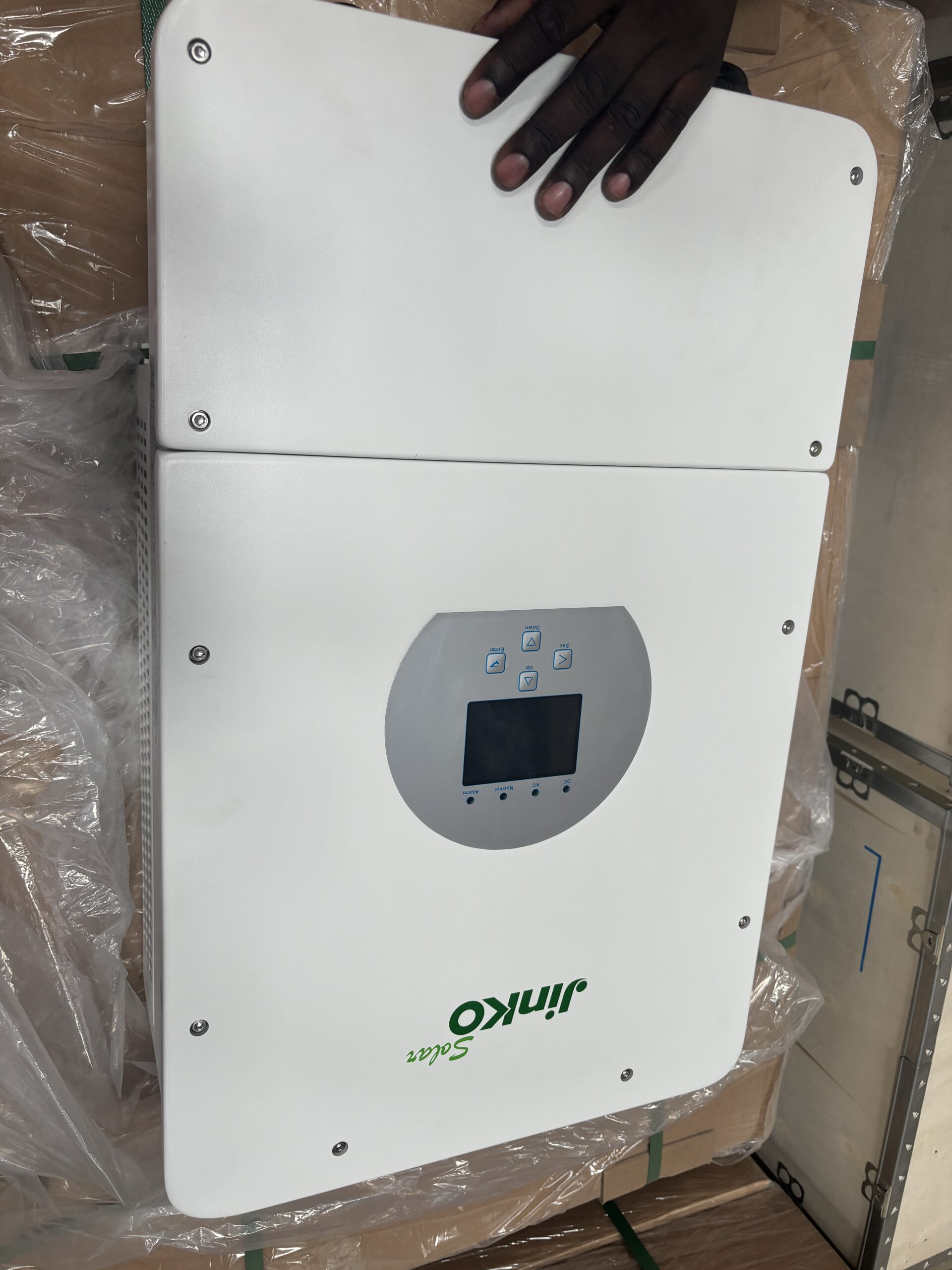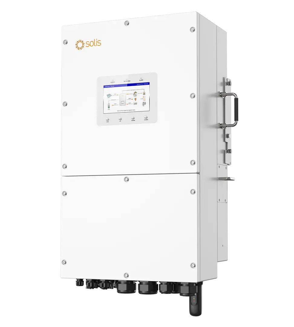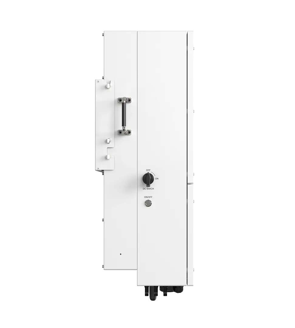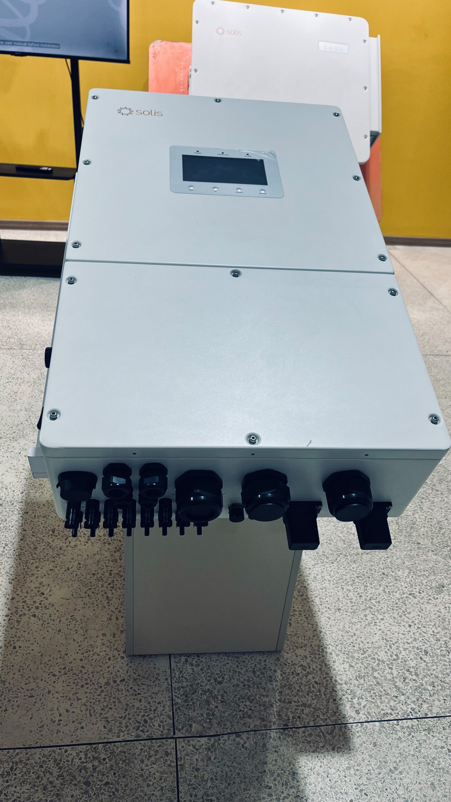
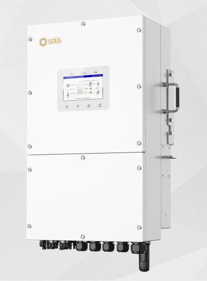
Description
Solis 14kW Single Phase Hybrid Inverter: The Largest in Its Series Whose Battery Rating Keeps Up
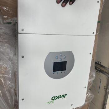
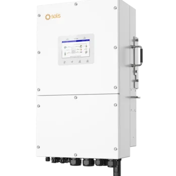
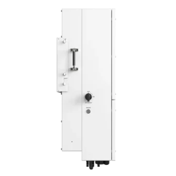
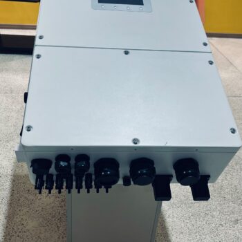
The Solis S6-EH1P14K03-NV-YD-L delivers 14000W from one phase and a 48V battery, drawing on a solar array of up to 28kW through three independent trackers. It is built for properties whose demand has passed the point where appliances must be used in turn: large residences, mixed use buildings, farms, lodges, schools and small commercial premises.
It is a different machine from the smaller low voltage units rather than a larger version of one. The DC platform runs higher, at 550V maximum with a 380V rated point, which is where its efficiency advantage comes from. There are three trackers instead of two, and six strings instead of four.
One characteristic deserves attention before any other, because it is the sort of thing that only emerges from putting the manufacturer’s own figures side by side.
Its battery rating actually supports its output. Producing 14kW from a bank at 51.2V calls for about 273A, and the inverter is rated for 290A. The next model up in the same series shares that identical 290A rating while needing roughly 313A to reach its nameplate, which it therefore cannot do from storage alone at that voltage. The 14kW model is the largest in this series where the two figures agree, and that agreement is what lets it deliver everything it claims during an outage rather than only while the grid is present.
Its usable solar input is shared with the model above it. The maximum the electronics will convert is 22.4kW on both. Carried on a 14kW nameplate that is a ratio of 1.6; carried on a 16kW nameplate it is only 1.4. The 14kW therefore makes fuller use of the same DC hardware.
Its charging appetite sets a real installation condition. Up to 95.5A from the grid, with 100A of passthrough, which effectively calls for a 100A service. This is covered in detail below because it decides feasibility.
Complete Technical Specifications Matrix
Solar PV Input Parameters
| Parameter | Value |
|---|---|
| Recommended maximum PV array size | 28kW |
| Maximum usable PV input power | 22.4kW |
| Maximum input voltage | 550V |
| Rated voltage | 380V |
| Start-up voltage | 100V |
| MPPT voltage range | 80V to 520V |
| Full output voltage range | 186V to 450V |
| Maximum input current | 40A per tracker |
| Maximum short circuit current | 50A per tracker |
| Maximum input power per tracker | 12kW |
| MPP trackers and strings | 3 trackers, 6 strings |
| DC connection | MC4 connectors |
Array Design: A Full Output Window With Both a Floor and a Ceiling
Four voltage figures appear in that table and they are commonly collapsed into one. Keeping them apart is what produces a string design that works in February as well as in July.
- 100V is where the trackers wake up, which governs how early in the morning the array begins contributing.
- 80V to 520V is where tracking takes place.
- 186V to 450V is where the inverter can produce everything it is rated for.
- 550V is the absolute limit, and exceeding it damages the input stage.
The consequence is that the full output band is considerably narrower than the tracking band, and it is bounded at both ends. A string can sit inside the tracking range and still be unable to support rated power, either because it is too short or because it is too long.
Temperature moves both boundaries, in opposite directions and at opposite ends of the day. Heat drives cell voltage down, costing something close to an eighth of it by the middle of a bright afternoon, which is the very moment the array ought to be at its most productive. Cold pushes it the other way, so the highest open circuit reading of the year arrives on a clear dawn before any sun has reached the glass. A string therefore has two tests to pass: stay above 186V when baking, and below 550V when freezing.
| Panels per string | Operating, moderate | Operating, hot roof | Open circuit, cold dawn | Verdict |
|---|---|---|---|---|
| 5 x 620W | Around 210V | Around 185V | Around 275V | Lands on the full output floor when hot |
| 6 x 620W | Around 252V | Around 222V | Around 330V | Practical minimum |
| 7 x 620W | Around 294V | Around 260V | Around 385V | Clear of every limit |
| 8 x 620W | Around 336V | Around 297V | Around 440V | Clear of every limit |
| 9 x 620W | Around 378V | Around 334V | Around 495V | Practical maximum |
| 10 x 620W | Around 420V | Around 371V | Around 550V | Arrives at the absolute ceiling |
Six to nine panels per string is the working envelope, with seven or eight the least demanding choice. Ten is where the cold dawn open circuit figure meets the 550V limit exactly, and a limit met exactly is a limit exceeded on the coldest morning of the year.
Six strings across three trackers means two strings sharing each tracker. Two things follow from that pairing, and both are comfortable. Two strings of modern panels present roughly 31A of short circuit current against the 50A each tracker permits. Two strings of nine 620W panels come to about 11.2kW against the 12kW each tracker will accept, so the per tracker power cap stays out of the way at any string length this inverter can use.
Filling the 28kW array allowance takes around forty five panels of 620W. Six strings of seven reach 26kW, and six strings of eight reach 29.8kW, which overshoots the allowance while remaining a legitimate design given that 22.4kW is the conversion ceiling in any case.
These figures are worked from a 620W panel of common voltage and current specification and are illustrative. Open circuit voltage and temperature coefficient vary between panel models, and both feed straight into the limits above, so final string design belongs to the panel actually chosen.
AC Output and Backup Power Capacities
| Parameter | Value |
|---|---|
| Rated output power | 14kW |
| Maximum apparent output power | 14kVA |
| Operation phase | Live, neutral and earth |
| Rated grid voltage | 220V or 230V |
| Rated grid frequency | 50Hz or 60Hz |
| Rated grid output current | 63.6A at 220V, 60.9A at 230V |
| Power factor | Above 0.99, adjustable 0.8 leading to 0.8 lagging |
| Current distortion | Under 3% |
| Grid input voltage range | 187V to 253V |
| Grid frequency acceptance | 45Hz to 55Hz, or 55Hz to 65Hz |
| Grid maximum input current | 95.5A at 220V, 91.3A at 230V |
| Backup rated output power | 14kW |
| Backup maximum apparent power | Twice rated power for 10 seconds |
| Backup switch time | Under 4ms |
| Backup rated output current | 63.6A at 220V, 60.9A at 230V |
| Backup overcurrent protection | 127A |
| Maximum continuous AC passthrough | 100A |
| Backup voltage distortion at linear load | Under 3% |
| Generator maximum input | 14kW, 63.6A at 220V |
| AC connection | Terminal block |
The Service Connection Decides Whether This Inverter Can Be Installed
Three currents in that table are larger than domestic electrical installations in this market are generally built to carry, and they need resolving on paper before anything is ordered.
Charging can draw 95.5A. That figure sits on top of whatever the building is consuming at the same moment, because the inverter does not pause charging while somebody switches on a cooker. The combined total is what the incoming main breaker sees.
Passthrough is rated at 100A. This is the clearest statement of what the unit expects. An inverter designed to pass 100A through to the loads anticipates a service in that class, and a service of half that rating turns the main breaker into the system’s real capacity limit regardless of what the inverter can do.
Output reaches 63.6A. An 80A protective device and 25mm squared conductors, which is a heavier circuit than most domestic consumer units are populated for. A sub board or a board replacement is usually part of the work.
Where the available service falls short, the position is not hopeless but it does have to be deliberate. Grid charge current can be capped in the configuration so the main breaker is never threatened, which costs charging speed and nothing else. Charging can be scheduled into the small hours when the building draws almost nothing and the whole service is free. The array, at up to 22.4kW of conversion, can carry most of the charging without touching the meter at all. Or the service can be upgraded, which is more often justified at this capacity than at any smaller one, because a property genuinely needing 14kW has usually outgrown its original connection.
What should not happen is the inverter being installed at full configuration against a service that cannot support it, because the symptom is a main breaker that opens without apparent pattern and takes the whole property down, including the inverter.
Backup Behaviour and a Note on Published Switching Figures
The model manual and the model datasheet both specify transfer to backup in under 4 milliseconds. Solis’s range level literature quotes under 10 milliseconds as a general figure spanning the wider series. Both appear here because they differ, and the two model specific documents are the ones describing this unit.
Four milliseconds falls well within the span a switched mode power supply can cover from the charge already held in its own capacitors. Desk computers, network equipment, screens and household electronics therefore ride straight through a utility failure with nothing to show for it. The practical result is that occupants tend to find out the power has gone from a neighbour or a darkened street, not from anything happening indoors.
Surge capability is twice rated power for ten seconds, which is 28kVA. That covers borehole pumps, workshop compressors, large air conditioning and estate gates starting into a fully loaded system. Overcurrent protection on the backup output operates at 127A.
Alongside the main backup output the inverter provides a manageable load output, which lets non essential circuits be shed automatically as the bank depletes so that the circuits that matter run longer. On a property of this size, where the difference between essential and convenient is wide, that setting does more for real backup duration than adding storage does.
48V Battery Management and BMS Communication Specifications
| Parameter | Value |
|---|---|
| Battery type | Lithium ion or lead acid |
| Battery voltage range | 40V to 60V |
| Maximum charge and discharge power | 14kW |
| Maximum charge and discharge current | 290A |
| Communication protocols | CAN or RS485 |
This is the specification that defines the inverter, and it rewards a moment’s arithmetic.
Power is current multiplied by voltage, so the current a 14kW draw requires depends entirely on where the bank is sitting in its discharge. At 51.2V, the resting voltage of a sixteen cell lithium iron phosphate bank, 14kW calls for about 273A against the 290A available. Full output is therefore genuinely available from storage, with roughly 850W of margin in hand.
| Bank voltage | Current needed for 14kW | Against 290A | Power actually available |
|---|---|---|---|
| 51.2V, resting | 273A | Within rating | Full 14kW |
| 48.3V | 290A | At the rating | Full 14kW, at the boundary |
| 48V | 292A | Marginally beyond | Around 13.9kW |
| 44V, deeply discharged | 318A | Beyond | Around 12.8kW |
Rated output holds down to roughly 48.3V, which covers the great majority of a lithium iron phosphate discharge curve, after which available power eases back gently rather than cutting off. By the time the bank is down at 44V it is being recharged rather than asked for everything, so in practice the taper is rarely met.
Set against the rest of the series this is what distinguishes the model. The smaller unit needs 234A at 51.2V and is rated for 250A, so it is matched. This one needs 273A and is rated for 290A, so it is matched. The larger unit carries the same 290A rating but needs around 313A, so it cannot reach its nameplate from the battery at that voltage no matter how large the bank. Fourteen kilowatts is where this series stops being able to grow its battery current, which makes it the point of best balance rather than merely a middle option.
The practical requirement that follows is a bank chosen on sustained current rather than on stored energy. Three packs of the common 100A class will supply 290A only with nothing to spare and no allowance for one pack ageing differently from the others; four packs, or two of the larger units carrying high continuous ratings, is the sounder arrangement. Energy capacity then lands somewhere between twenty and forty kilowatt hours as a consequence of the current requirement rather than as the starting point.
Linking the pack over CAN or RS485 hands the inverter the battery’s own account of itself: charge state, cell temperatures and the current limits the management system is currently enforcing. Once 290A is in play that link is no longer a refinement. Judging a bank by terminal voltage is imprecise at any current, and at this one the gap between what the pack will actually tolerate and what the inverter assumes it will tolerate is precisely where hardware gets destroyed.
Mechanical, Environmental and Efficiency Ratings
| Parameter | Value |
|---|---|
| Maximum efficiency | 97.6% |
| European weighted efficiency | 97.2% |
| Battery charged from PV | Above 94.9% |
| Battery charged from AC | Above 94.33% |
| Battery discharged to AC | Above 93.51% |
| Topology | Transformerless |
| Cooling | Intelligent fan cooling |
| Noise emission, typical | Under 65 dB(A) |
| Protection degree | IP66, rated Type 4X, indoor or outdoor |
| Protection class | I |
| Overvoltage category | II on PV and battery, III on mains, backup and generator |
| Operating temperature | -25C to +60C |
| Maximum altitude | 4000m |
| Dimensions | 464 x 763 x 282mm |
| Weight | 48.5kg |
| Parallel expansion | Up to 6 units, giving 84kW |
A 97.6% peak with a 97.2% European weighted figure is the strongest showing in the low voltage lineup, and the weighted number is the one to read. It samples behaviour across the spread of loads an inverter meets in service instead of at its single most flattering point, so a gap of four tenths of a percent indicates the unit holds its efficiency whether it is idling at dawn or working hard at noon.
The gain traces back to the DC platform. This series runs a 380V rated input where the smaller low voltage models run 330V, and a higher voltage for the same power means less current through the conversion stage, where losses rise with the square of current. The higher voltage ceiling is not only about fitting longer strings; it is where the efficiency comes from.
Round trip figures are published separately and are worth noting, because they govern how a system should be operated rather than how it should be specified. Storing solar energy and returning it later costs around eleven percent all told. Using generation directly, at the moment it is produced, avoids that cost entirely, which is the argument for aligning heavy consumption with the middle of the day wherever the household’s routine allows.
Three physical characteristics shape installation. The unit weighs 48.5kg, which is a two person lift onto a wall that can genuinely carry it, so masonry or a properly fixed steel frame rather than a partition. It measures 464 by 763 by 282mm, which needs planning for alongside clearance for airflow and cable entry. And the published noise figure is under 65 dB(A), which is around the level of ordinary conversation. Fan cooling is what keeps a 14kW converter in an enclosure of this size, and the honest consequence is that this is not equipment for a bedroom wall or a quiet study. A utility room, garage, plant room or exterior wall away from living space is the right place for it.
Rated operation to 4000m is the most generous figure in the low voltage lineup and puts every Kenyan site comfortably inside the envelope, highland locations included, which is not true of all imported equipment and its common 2000m limit. Sealing is IP66 and additionally classified Type 4X: dust cannot enter and the housing tolerates a directed jet of water from any angle. Mounting outside is therefore perfectly proper, with the caveat that shade extends both the working life and the output of anything hung on a wall in this climate.
Real-World Appliance Compatibility and System Load Limits
At 14kW the useful question is not what the inverter will run but what it removes the need to think about. Below this capacity a large Kenyan property is managed: showers are taken in turn, the cooker waits for the kettle, the pump runs when the air conditioning is off. At 14kW that sequencing largely disappears.
| Everything running together | Approximate total | Position |
|---|---|---|
| Two instant showers | Around 9kW | 5kW still in hand |
| Two instant showers and a full cooker | Around 12kW | 2kW still in hand |
| Base load, two air conditioners, borehole pump and two showers | Around 13.3kW | Inside the rating |
| Two showers, cooker and kettle | Around 14kW | At the rating |
| Two showers, cooker, kettle and an oven | Around 17kW | Beyond the rating |
Two bathrooms can be in use while a meal is cooked and the borehole refills the tank. The ceiling appears only when three or four deliberately heat producing appliances are combined with a shower load already running, which is an unusual household moment rather than a daily one.
Motor starting is covered by 28kVA for ten seconds, a margin wide enough that pump and compressor inrush stops being a design consideration and becomes a detail.
The important qualification is the one already made. These figures describe what the inverter will deliver. Whether it delivers them from the battery during an outage depends on the bank supplying 290A, and whether it delivers them while charging depends on the incoming service. The inverter is rarely the binding constraint at this capacity; the battery and the service usually are.
Operational Modes and Smart Energy Management
On-Grid, Off-Grid and Self-Consumption Configurations
Self consumption sends generation to the loads first, stores what is left, and draws from the utility only for the shortfall. It is the right default for nearly every installation here, lowering the bill without relying on an export arrangement.
Backup operation takes over when the utility fails, running the protected circuits from stored energy and live generation together. A property with no utility connection at all can be set to run this way permanently, and the series also supports operating from solar alone where storage is being added in stages.
Grid charging replenishes the bank from the mains anywhere between 187V and 253V. At up to 95.5A it is quick, subject to the service capacity question dealt with above.
Retrofit alongside existing generation is supported, so a property that already has a grid tied array can add storage and backup without rebuilding the original installation, with export control available where the connection requires it.
Peak Shaving and Time-of-Use Programming
Charge and discharge windows are programmable, which turns the battery from a reserve into a scheduling instrument.
Peak shaving suppresses the maximum demand figure recorded against the meter, by meeting the heaviest part of the day from the bank and the array instead of buying it. Premises billed on demand, or constrained by an agreed capacity, gain from this directly. At 14kW the volume being shifted is substantial enough that it can move a site into a different tariff band rather than simply trimming a bill.
Time of use programming does the opposite job: it buys and stores while the supply is dependable, then keeps that energy in reserve for the part of the day when it is not. On sites where outages arrive at roughly predictable hours, positioning a charge window just before them means the premises crosses the gap with nobody aware of it.
Scheduling earns more at this capacity than at any smaller one, simply because of how much energy crosses the inverter daily. Half an hour spent matching windows to the building’s real rhythm, rather than leaving factory settings in place, is repaid continuously thereafter.
Generator Integration and Automatic Signal Control
A dedicated generator input accepts up to the full 14kW, with several connection arrangements and automatic control available.
A generator rated to the inverter’s full input is a meaningful capability, because it means the machine is not merely supporting the load but can simultaneously drive charging at high rate. A short run therefore converts into stored energy that carries the property through a long quiet evening, provided a charge window is aligned with the generator’s running hours. Without that alignment the fuel goes into whatever happens to be switched on at the time.
Generator sizing has to account for the combined figure, since the inverter will charge at full rate alongside serving the building. Unattended starting additionally needs the generator to provide a remote start facility and the control wiring to be installed, which many smaller sets sold locally do not offer.
Installation, Cable Sizing and Protection Guidelines
Recommended AC and DC Circuit Breakers and Cable Cross Sections
The figures below derive from the rated currents, taking each protective device at no less than 1.25 times the continuous value and then stepping up to the nearest size actually manufactured. Treat them as a point of departure. What is finally installed has to answer to measured cable runs, how those cables are bunched, the temperature they sit in, and the regulations in force.
| Circuit | Design current | Protective device | Cable, short run |
|---|---|---|---|
| PV, per string | 20A, being the per string share of the 40A tracker rating | 25A DC, rated beyond 550V | 4mm² double insulated solar cable |
| Battery to inverter | 290A, rising as the bank empties | 400A DC | 120mm², or paired 70mm² runs |
| AC output to loads | 63.6A | 80A, 2 pole, Type C | 25mm² |
| AC input from grid | 95.5A | 125A, 2 pole | 35mm² |
| Backup passthrough | 100A | 125A, 2 pole | 35mm² |
The battery circuit is the one that punishes shortcuts. At 290A the conductors are heavy enough to need proper routing and support, lugs must be crimped with the correct die rather than squeezed with pliers, and every termination needs tightening to the figure the manufacturer specifies. Resistance anywhere along that path becomes heat at the joint and voltage that never arrives at the inverter, and at this current a loose connection is a fire risk rather than an inefficiency. Keep the run short, under two metres where the layout permits, and keep the two poles of equal length.
Where a single 120mm squared conductor is awkward to terminate, two parallel 70mm squared runs per pole are often the more practical answer, provided both runs are the same length and the busbar arrangement actually shares current between them.
On the DC solar side, voltage rating deserves as much attention as current rating. Nine panels in series approach 495V once the glass has cooled overnight, and a device sold as a 250V DC breaker cannot safely interrupt that circuit whatever its ampere figure claims. Everything protecting the array should be rated beyond 550V.
Combiner Box and Built-in Safety Protections
| Protection | Status |
|---|---|
| DC surge protection | Yes |
| AC surge protection | Yes |
| Ground fault monitoring | Yes |
| Residual current monitoring | Yes |
| DC reverse polarity protection | Yes, on the PV input |
| Output overcurrent protection | Yes, operating at 127A |
| Integrated AFCI 2.0 | Optional |
Arc fault detection is an option rather than standard fitment, and across six strings it is the option most clearly worth taking. Six strings mean six times the connectors, terminations and junctions of a single string array, each one a place where a joint can loosen through thermal cycling or corrode through a decade of rain and dust on a hot roof. The detection circuitry recognises the electrical signature of an arc as it forms and shuts the input down before heat turns into fire. On an array feeding 22.4kW through a roof, that is cheap protection.
With six strings arriving from what is usually more than one roof plane, a combiner enclosure stops being optional. It gives isolation at the array rather than only at the inverter, a mounting position for surge protection close to where surges enter, and an orderly transition from six string cables into three tracker feeds.
The surge protection inside the inverter, on both the DC and AC sides, is built for transients travelling along conductors. A nearby lightning strike delivers energy of an entirely different order. Storm prone districts, and the lakeside counties above all, need external arrestors and a properly constructed earth specified from the beginning rather than retrofitted after a loss.
Lithium Battery Compatibility, CAN Bus and RS485 Protocols
Battery communication runs over CAN or RS485, and the approved register for Solis energy storage inverters extends well past a hundred manufacturers. A register of that size has a concrete benefit: storage is not tied to one supplier’s roadmap, and replacing a pack in year seven is an ordinary purchase instead of a hunt for discontinued stock.
Of the approved packs, those obtainable without difficulty through local supply include Hubble, Vestwoods, Dyness, Felicitysolar and Pylontech. Also listed, and brought in against a specific project, are Taico, Oliter, Sunwoda, Soluna, Shoto, BSLBATT, Narada, LG Energy Solution, Freedom Won and BYD.
At this capacity the selection criterion is the pack’s continuous current rating, and it should be read from the pack’s own datasheet rather than inferred from its capacity. A bank assembled to reach 290A reliably is what allows the inverter to perform as specified during an outage, and a bank assembled to reach a target in kilowatt hours may or may not manage it.
Approval attaches to specific models rather than to brands, and registers are revised as products enter and leave the market. Protocol selection and pin assignment differ between manufacturers, and getting both right is what gives the inverter a true account of the pack instead of an estimate. Some approvals apply only in particular markets or to particular firmware revisions.
Pairing an unapproved pack risks damage to both the inverter and the battery, and forfeits warranty cover on each. We verify the match against the current register, make up the correct communication lead for the pack being supplied, and set the protocol during commissioning.
Lead acid banks are supported and operate without any communication link, which places correspondingly more weight on configuring charge voltages, absorption times and temperature compensation properly at handover.
Monitoring, Configuration and Smart App Setup
Local operation is through a 7 inch LCD screen on the unit, with Bluetooth and the app for configuration at close range. Remote monitoring runs on the SolisCloud platform, with cellular, WiFi or LAN connectivity available as options, presenting generation, consumption, battery condition and grid interaction.
Beyond confirming the app connects, five tasks belong in commissioning on a system of this size.
Cap the grid charge current to suit the service, as a recorded decision rather than an oversight. On a constrained supply this is the single setting that prevents nuisance tripping.
Set the charge and discharge windows around the building’s actual pattern instead of leaving the factory arrangement in place.
Confirm the battery link is live rather than merely connected. Real pack data, including cell level detail, should be visible. A state of charge derived from voltage alone indicates the link has not come up, and at 290A that matters.
Assign the manageable load output deliberately, so the circuits that get shed first are the ones the household can afford to lose.
Record a reference output figure on a clear day shortly after handover. Without a baseline, gradual decline from soiling, new shade or a developing string fault is very hard to distinguish from ordinary weather later on.
Certifications, Compliance and Grid Standards
Solis inverters are manufactured by Ginlong Technologies, a publicly listed company with a longer operating history than most names presently in this market. On equipment where a warranty claim may arise eight or ten years after purchase, the manufacturer’s own durability forms part of the specification.
The grid connection standards listed for this series include NRS 097-2-1, IEC 62116, IEC 61727, IEC 60068, IEC 61683 and EN 50530, with safety and electromagnetic compatibility under IEC and EN 62109-1 and 62109-2 and EN 61000-6-2 and 61000-6-3. Certificates against EN 50549-1 and EN 50549-10 are published for the series, along with an IEC 63027 certificate covering arc fault detection.
One entry in that list is worth drawing out for buyers here. NRS 097-2-1 is a Southern African grid code, and its presence indicates the unit has been assessed against the conditions of an African network rather than only against European ones. Equipment engineered for voltage that wanders and supply that comes and goes behaves differently from equipment engineered for a stable grid, and the wide 187V to 253V acceptance window on the input reflects the same design intent.
Several compliance requirements appear as physical behaviour rather than as paperwork. Anti islanding disconnects the inverter when the utility disappears, so the array cannot energise conductors a technician may be working on. Ground fault and residual current are monitored continuously. Power factor adjusts across 0.8 leading to 0.8 lagging, while current distortion stays under 3% on the grid side and voltage distortion under 3% on the backup output at linear load. Protection class I applies, with overvoltage category II on the solar and battery connections and category III on mains, backup and generator terminals.
Grid connection in Kenya is regulated by the Energy and Petroleum Regulatory Authority, whose requirements apply to the installation as a whole. Standards mark documentation from KEBS attaches to a consignment and not to a model number, so it is the delivered batch that carries it. Our practice is to hand over the certification covering the actual unit supplied, with the work itself performed by technicians licensed by the regulator.
Package Contents
Supplied with the inverter: the wall mounting bracket and its fixings, MC4 connectors for the solar inputs, terminal block covers, and the product documentation.
Four items vary between supply routes and belong on any quotation being compared:
- Communication stick for SolisCloud, in cellular, WiFi or LAN form depending on what the site can offer.
- Energy meter or current transformer, without which peak shaving and export control operate from an assumption rather than from measured demand.
- Battery communication lead, which has to match the specific pack, since pin assignments are not standardised across manufacturers.
- Printed documentation, now often replaced by a download.
We confirm contents for the specific unit being bought before an order is placed, and the battery communication lead is made up for the chosen pack rather than left for the customer to source.
Warranty Terms, Local Technical Support and Registration
The standard warranty published for this series is five years, with extension available to twenty. Because terms are varied by region and by supply route, the period and conditions applying to a particular unit are stated in writing on the invoice rather than offered as a general claim.
Three things are settled on every inverter we supply.
What the cover includes. Whether labour accompanies parts, and whether a replacement unit keeps the property running while a failed one is assessed. On a system carrying a whole premises, that second point matters more than the headline period.
Registration. Manufacturers frequently grant the full term only where the installation is registered inside a defined window, applying a shorter default otherwise. Where that condition applies, we complete it.
How a claim is made. Factory cover is worth only what can be acted on locally. Diagnosis, documentation and dealings with the distributor sit with us, so equipment is never shipped abroad by the customer.
Support runs past warranty matters into commissioning configuration, battery protocol setup, firmware revisions and fault diagnosis, handled locally by EPRA certified technicians.
At 14kW the inverter is rarely what limits the system. The battery’s continuous current rating and the capacity of your incoming service are, and both can be checked before anything is ordered.
Send us the rating on your main breaker, the roof planes and orientations you have available, and the heaviest set of appliances that might genuinely run together. We will confirm whether the service supports the charging, lay six strings out against your roof inside the 186V to 450V full output window, and specify a bank that actually delivers 290A. To model a whole property from first principles, start with our Solar Calculator. For a costed proposal covering inverter, battery, array, protection, board work and installation, submit the site through My Quote.